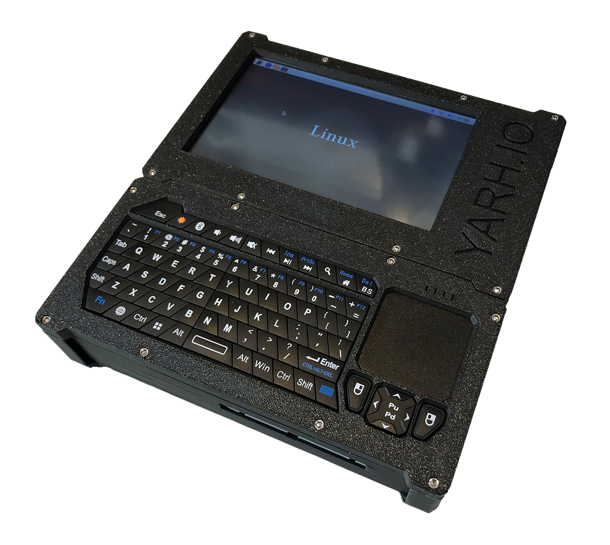
YARH.IO MKI
Raspberry Pi 3B+ Hackable Linux Handheld
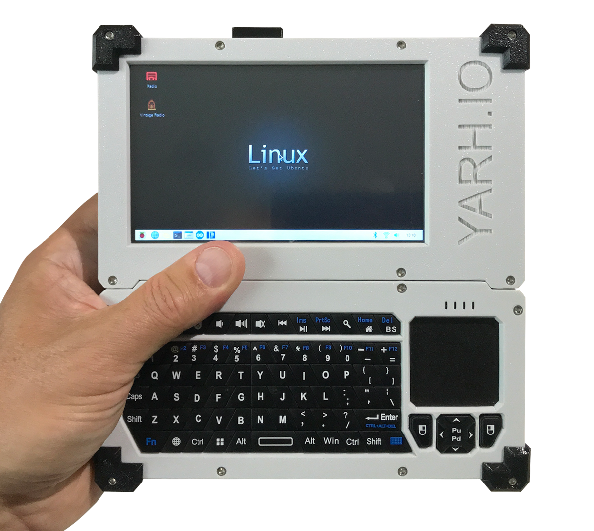
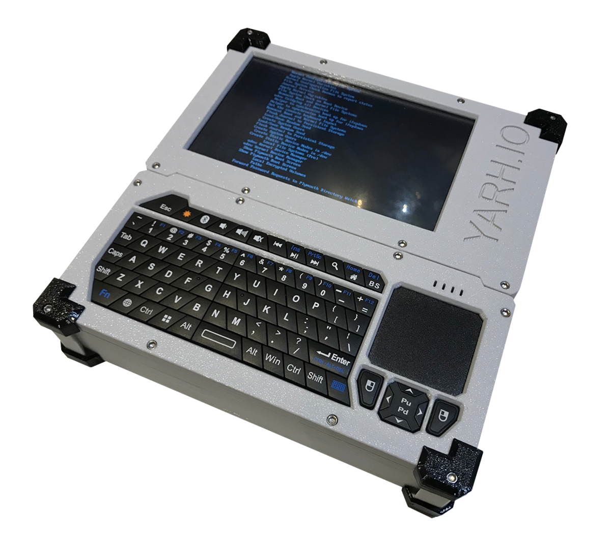
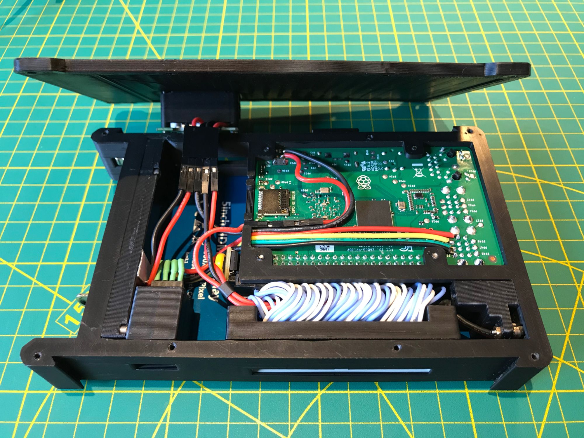
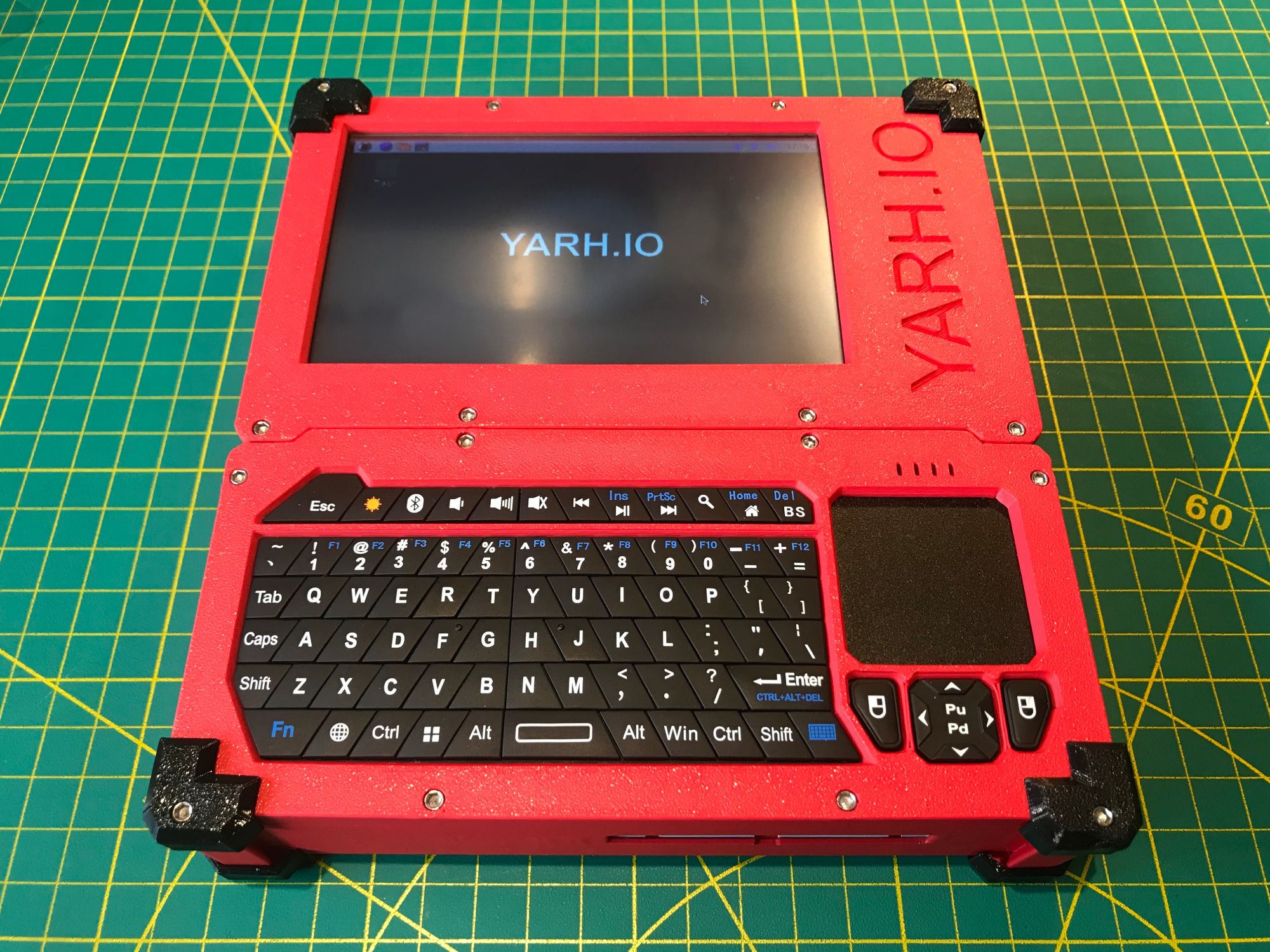
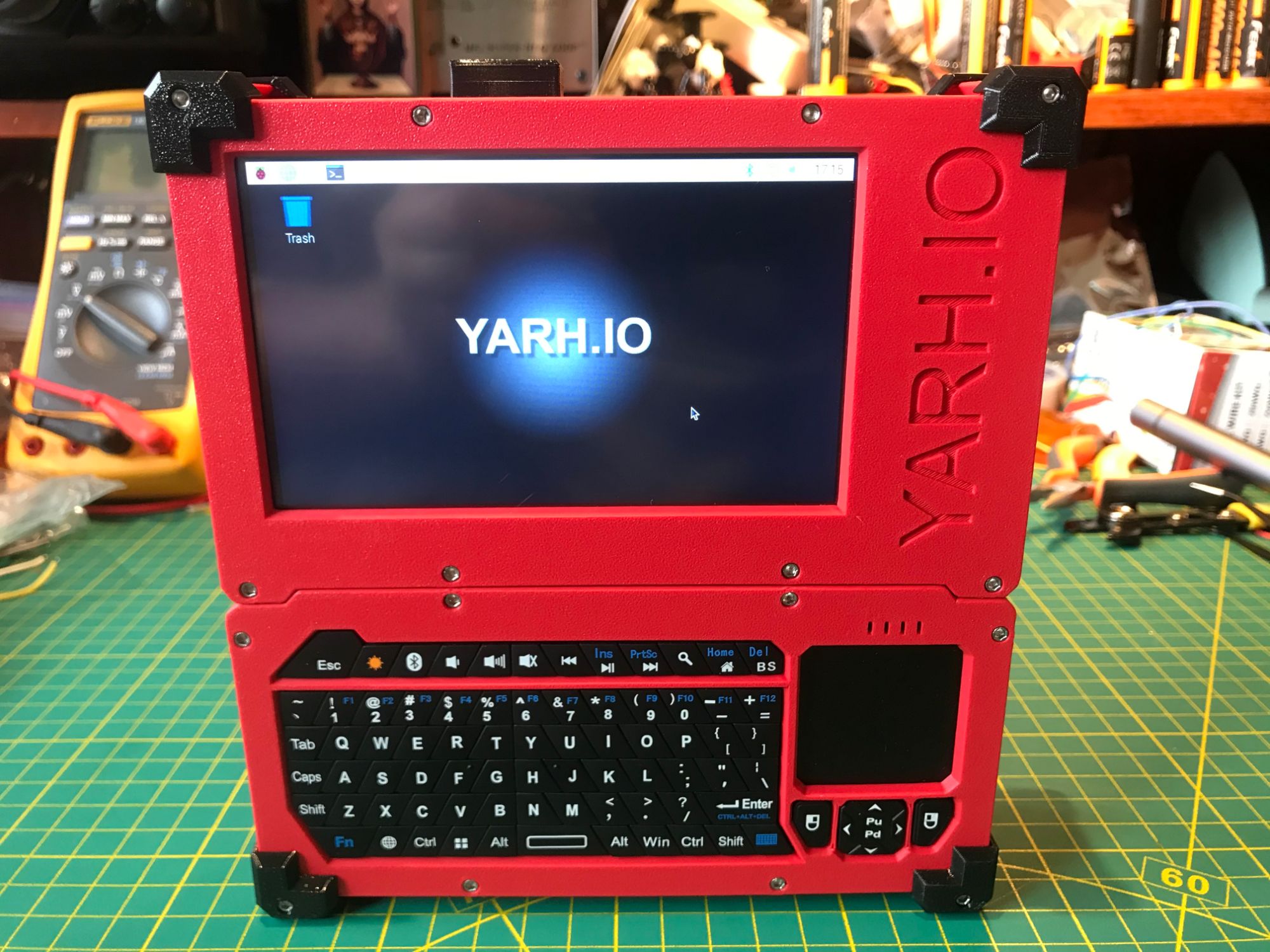
The first YARH.IO handheld — a modular Raspberry Pi 3B+ device built for hackability. Every component is accessible and replaceable. Exposed GPIO, I2C bus, and a fully open design make it a platform for experimentation, not just a finished product.
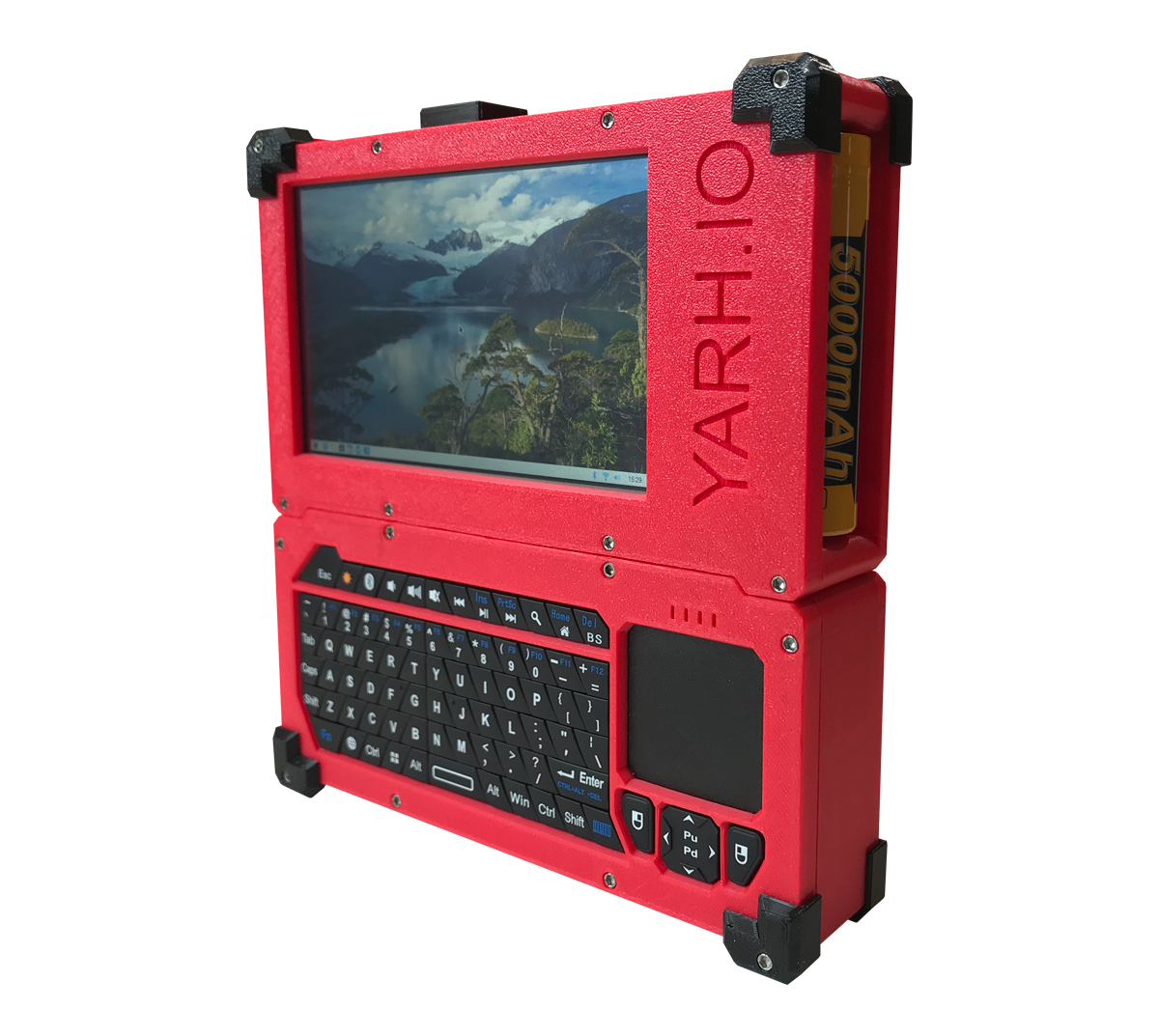
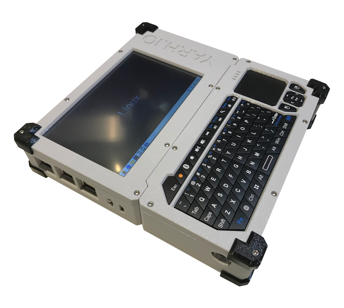
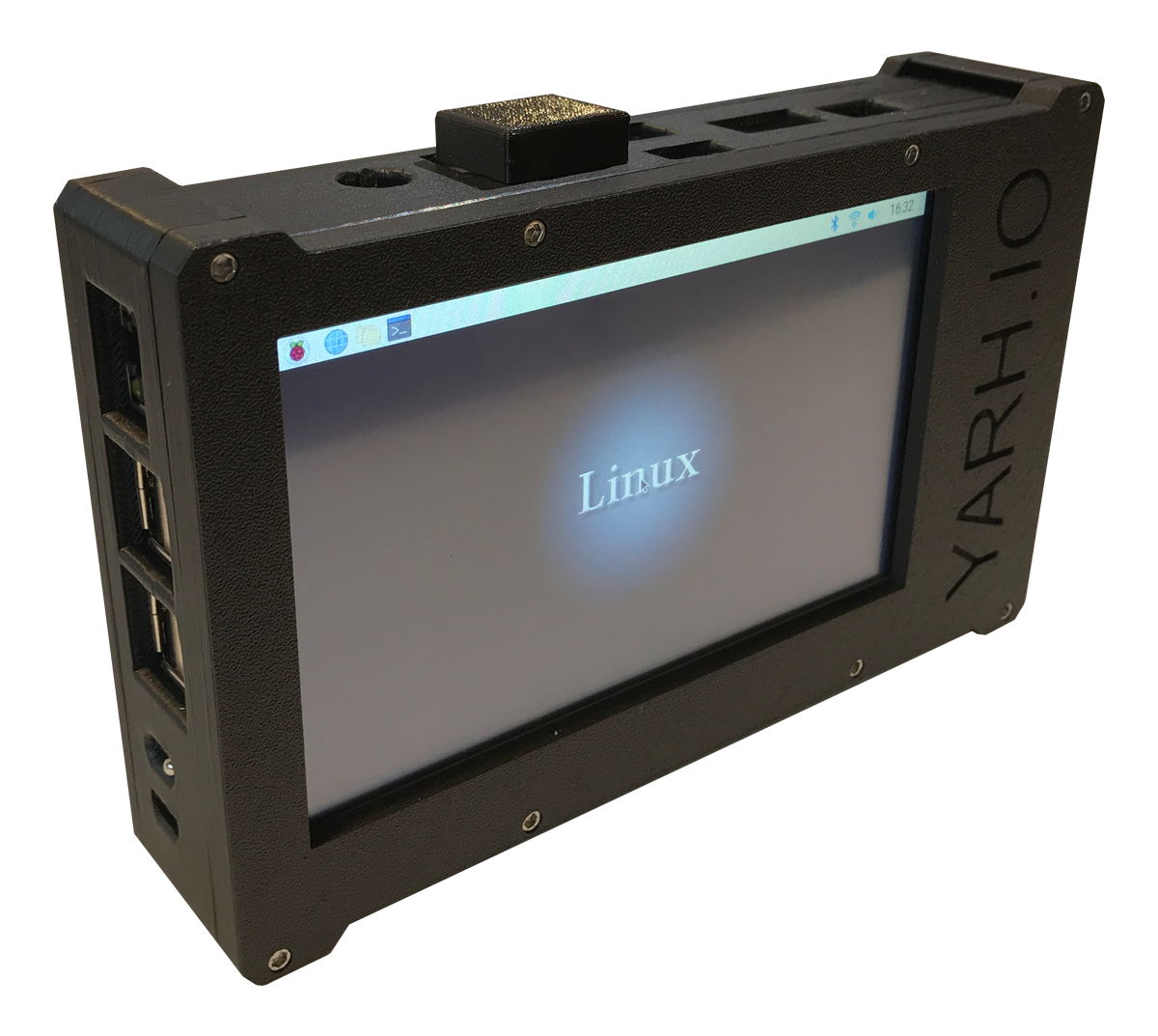
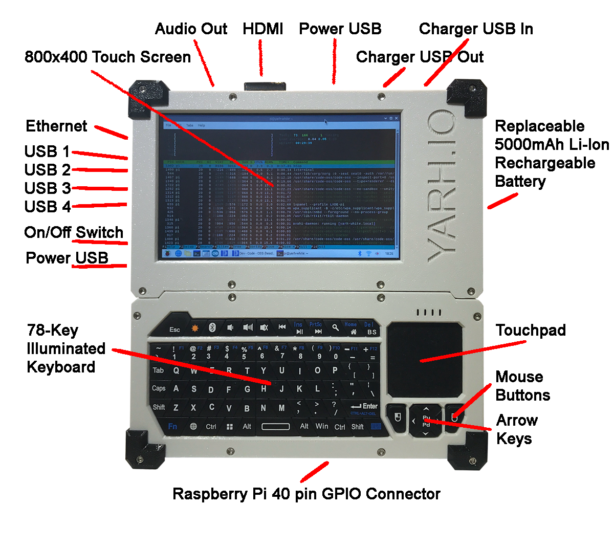
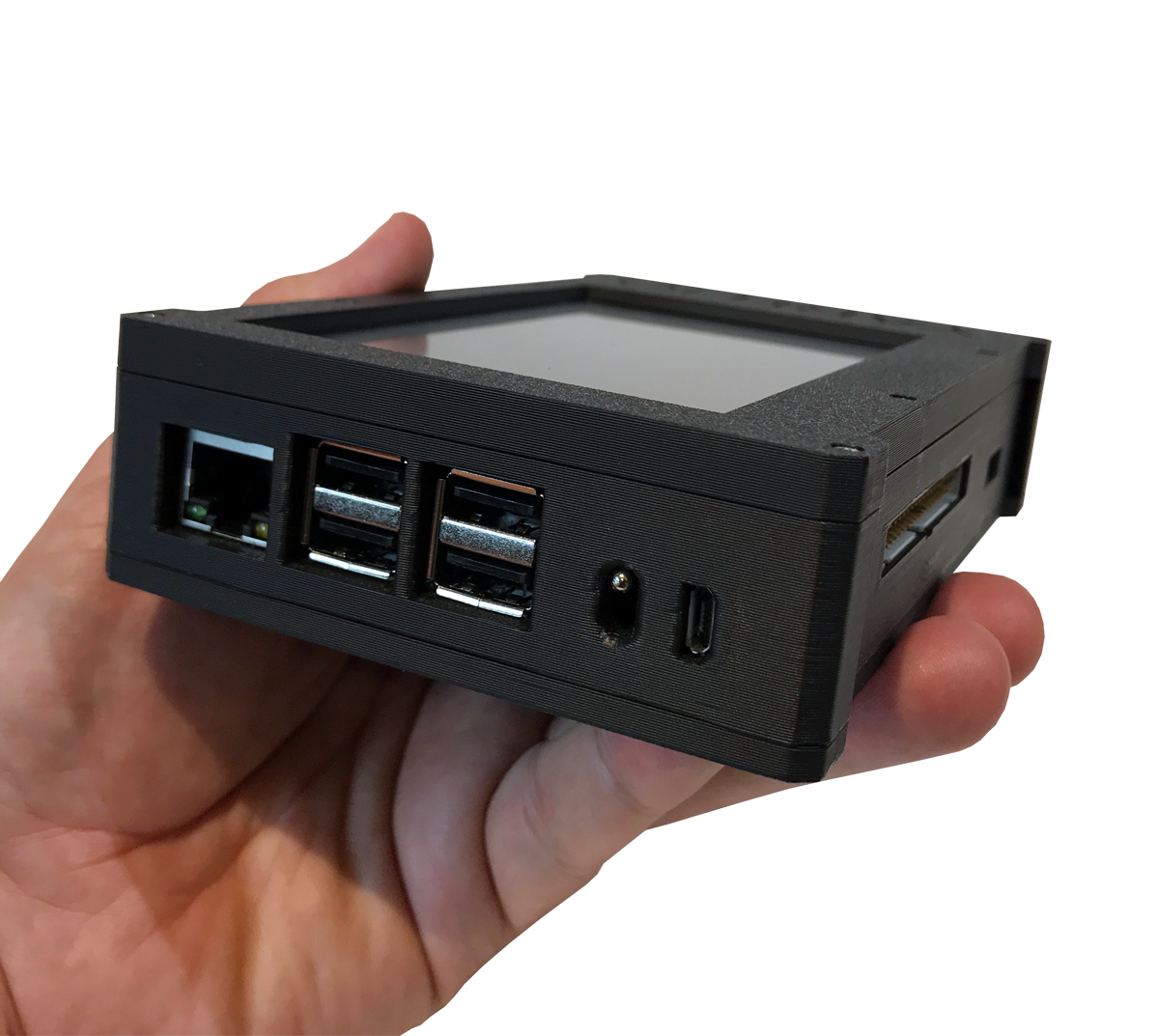
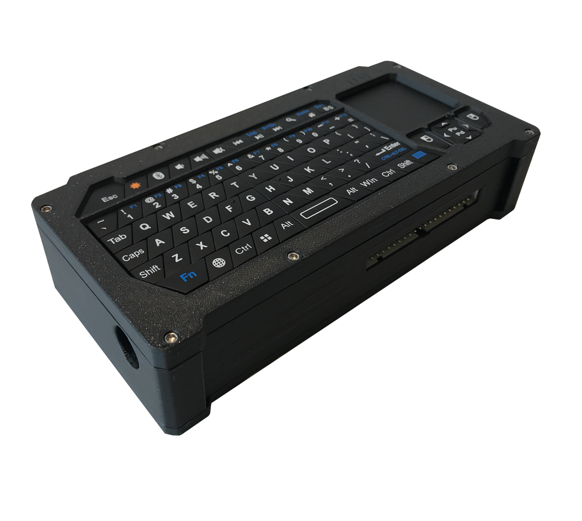
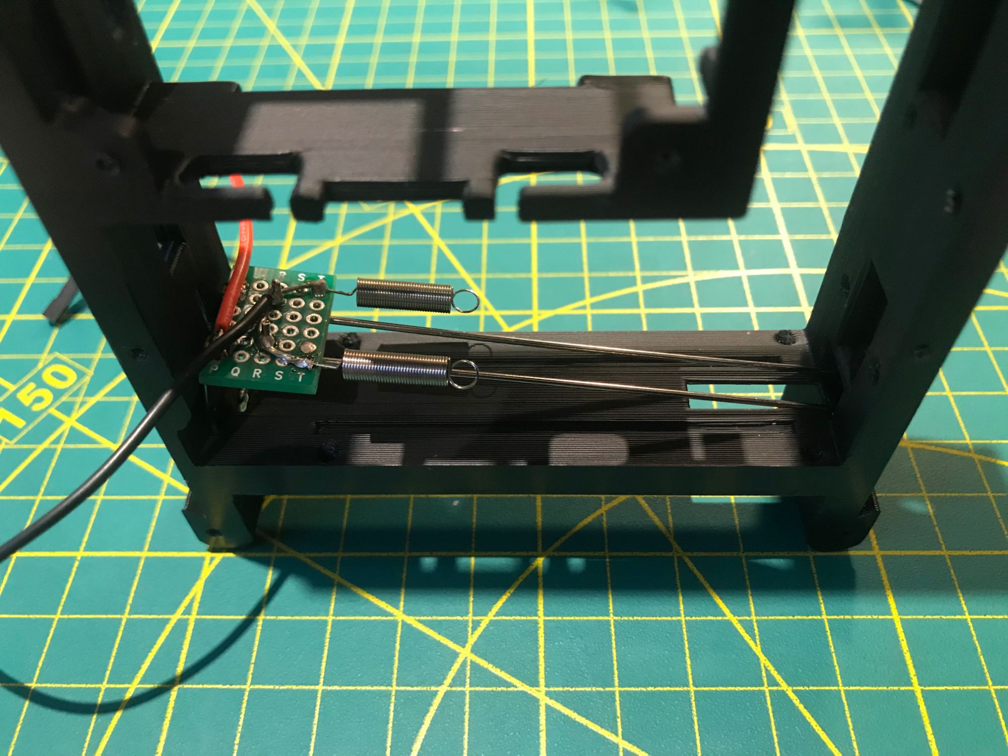
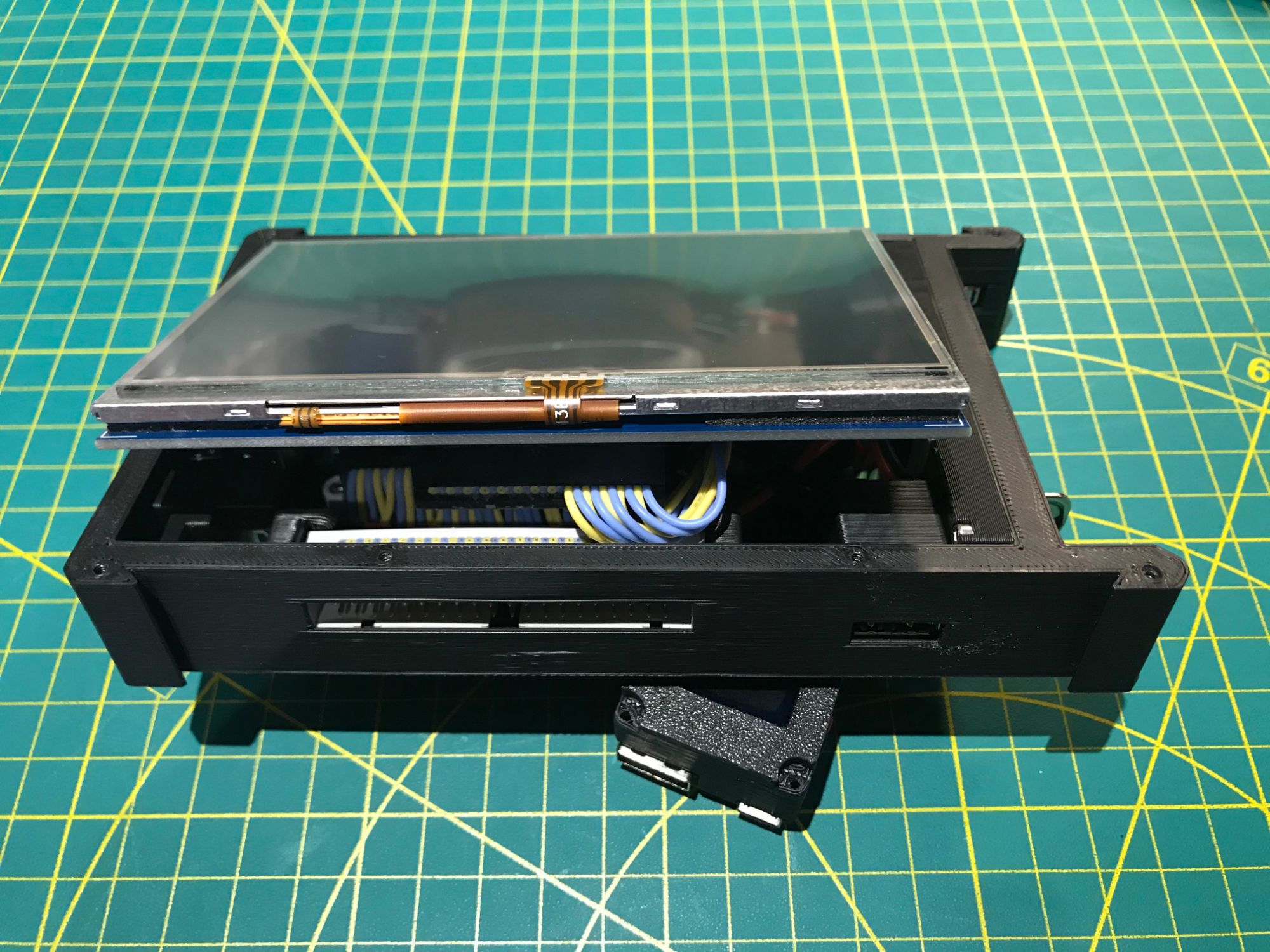
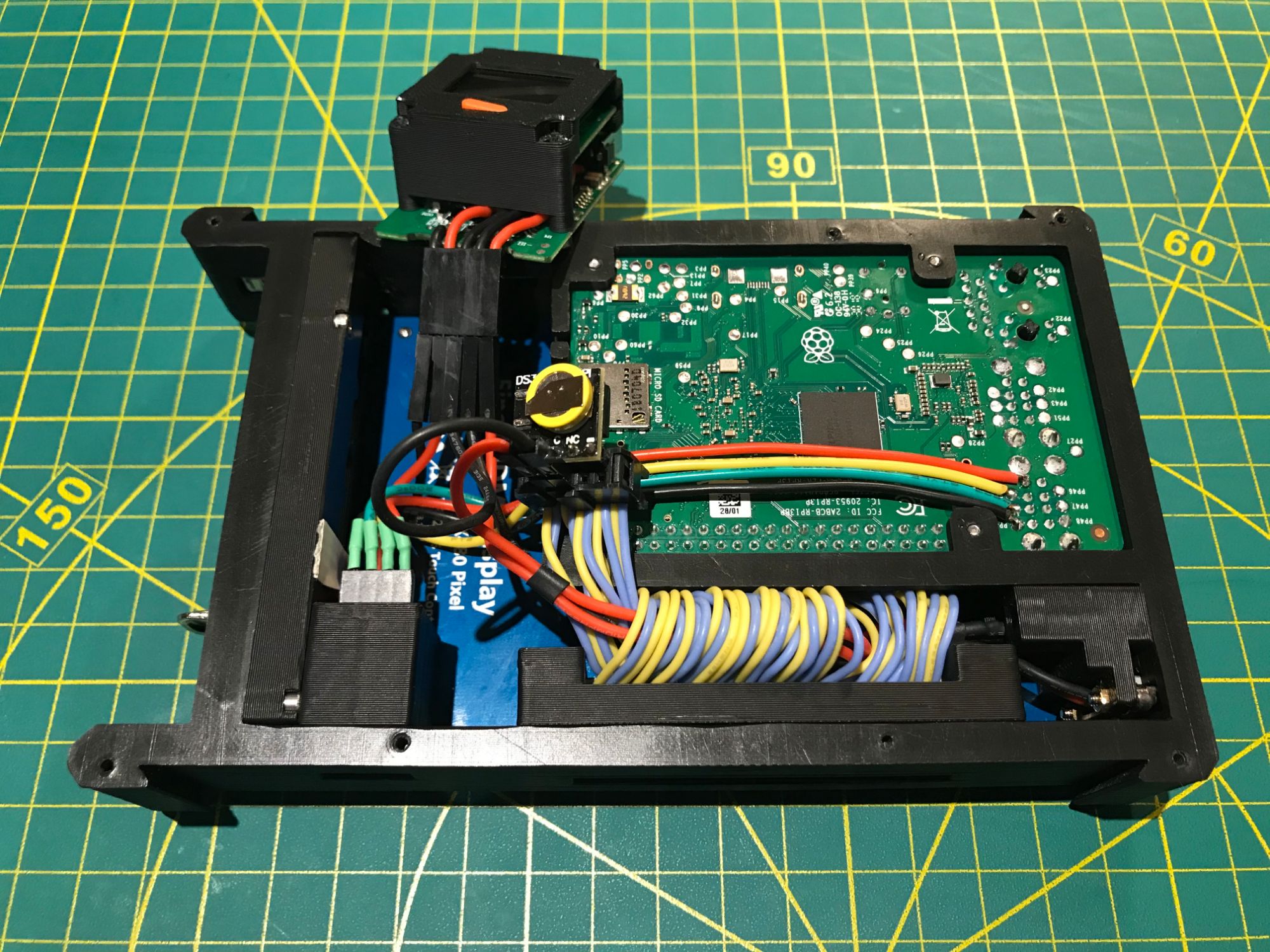
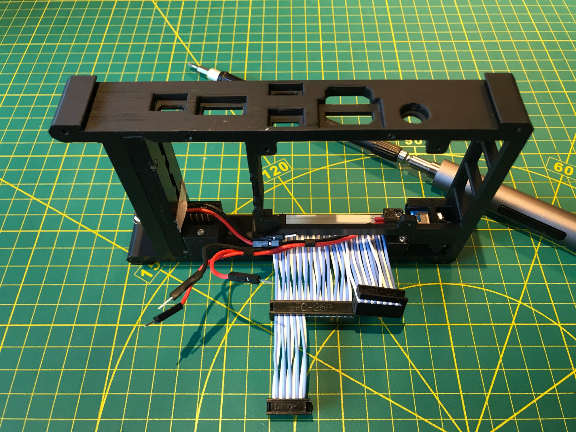
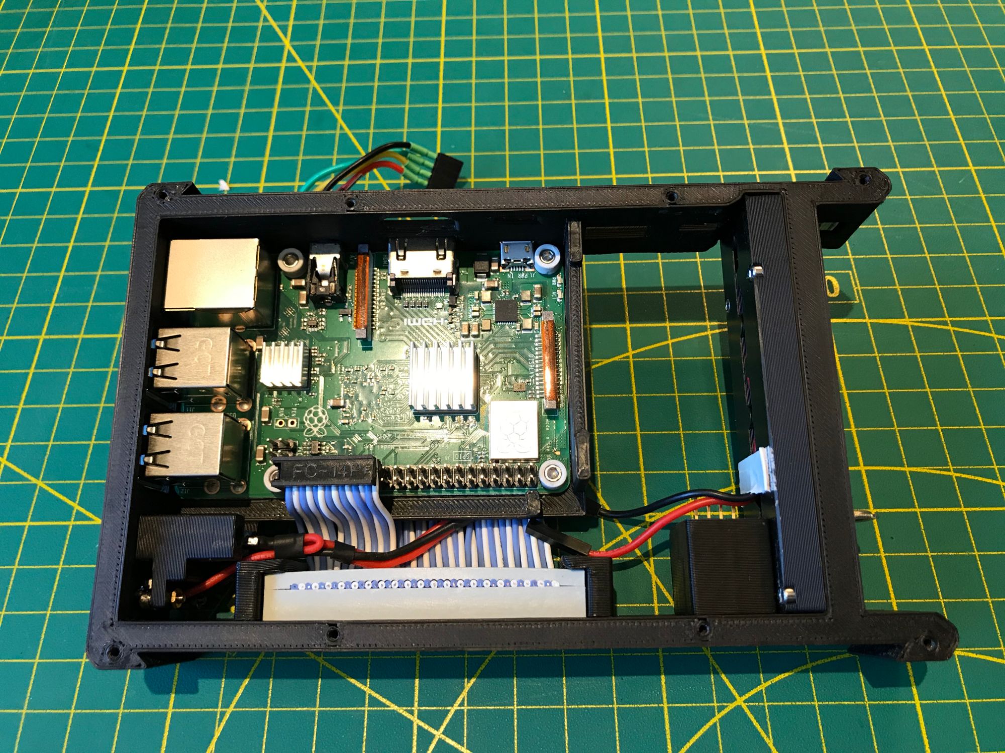
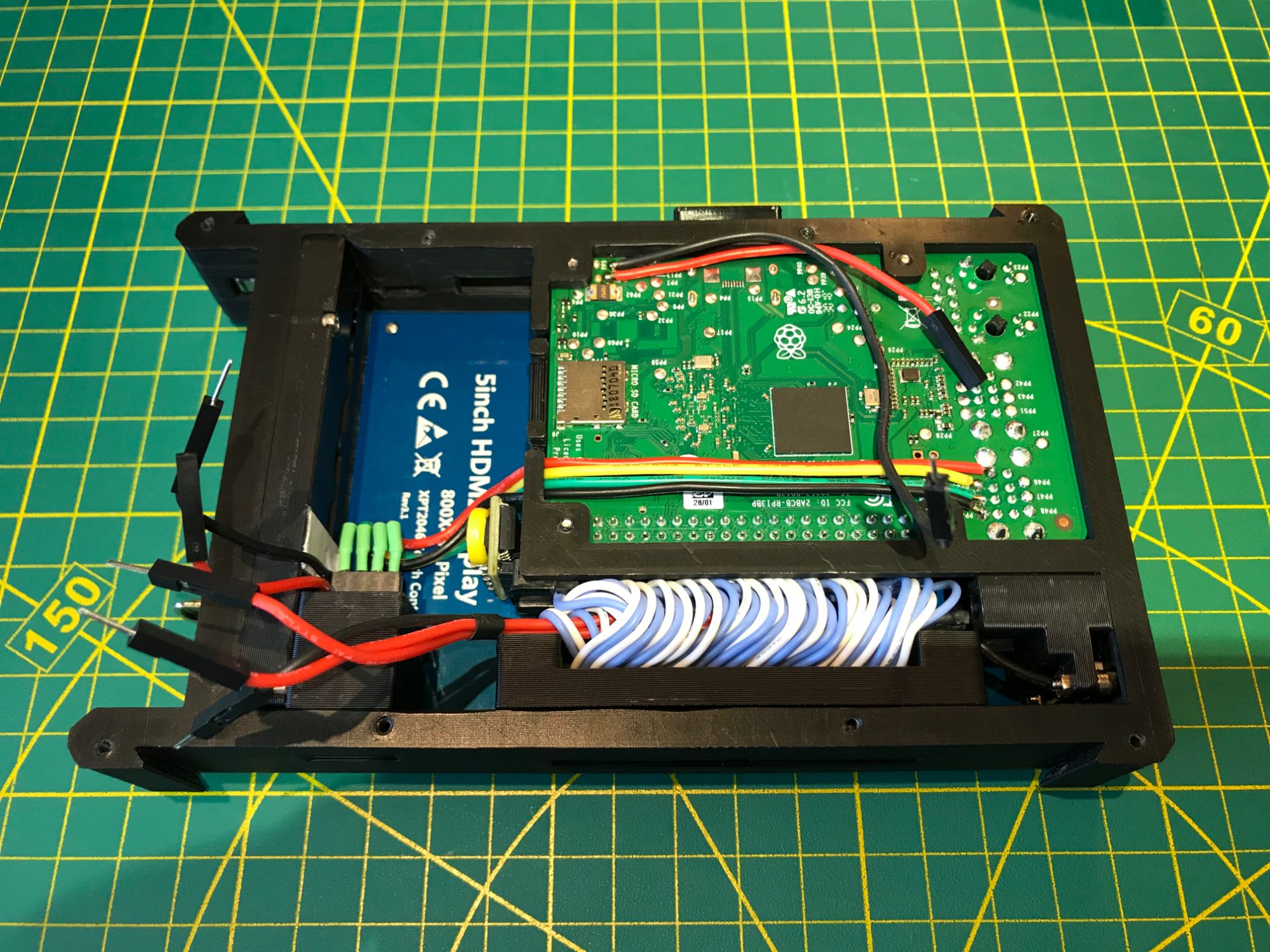
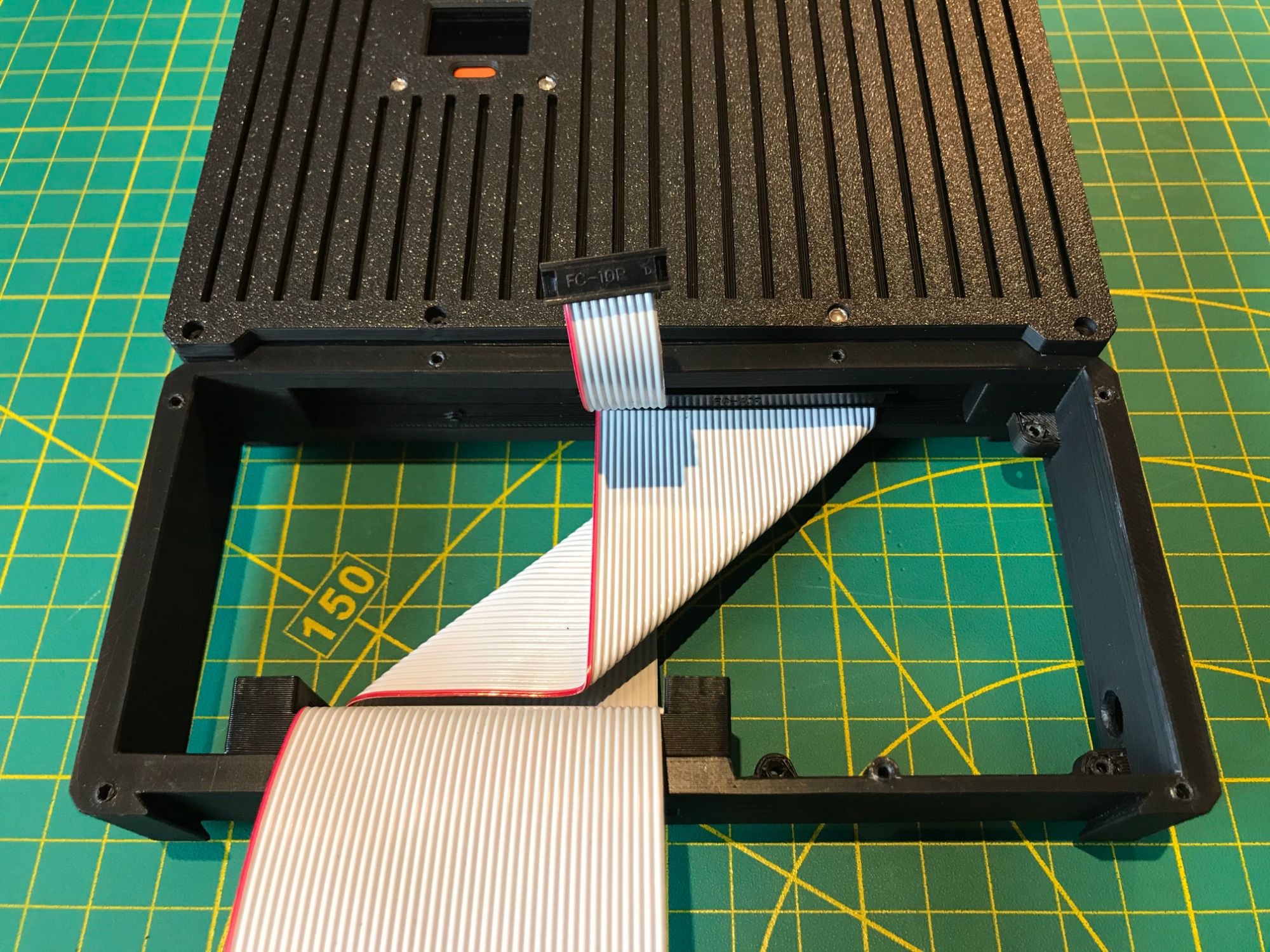
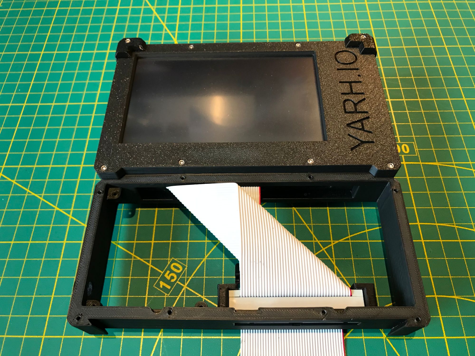
The MKI uses a modular architecture where the main module houses the Raspberry Pi 3B+, display, power supply, battery, RTC, and GPIO ribbon cables. The extension module connects underneath and carries additional hardware — USB devices, LoRa radios, RFID readers, IR transceivers, or a Pi-DAC+ for audio. A shared USB connector and a full GPIO header on the bottom of the main module make the interface between the two. The width of the main module is set by the keyboard dimensions for comfortable handheld use.
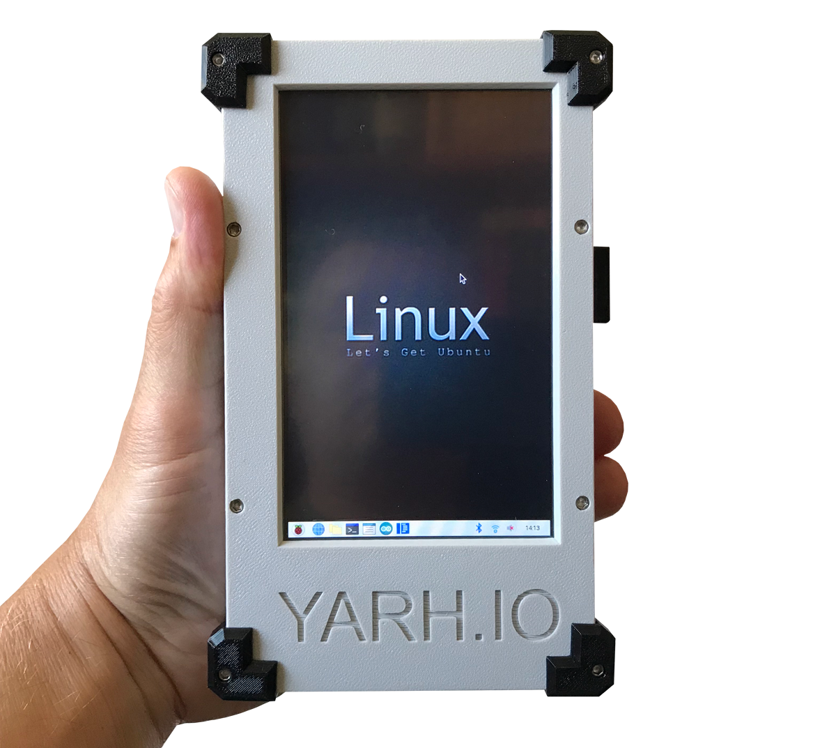
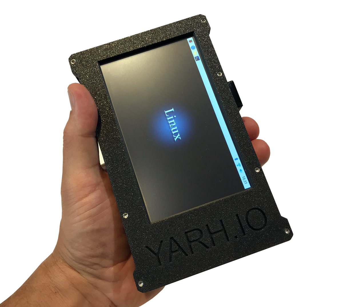
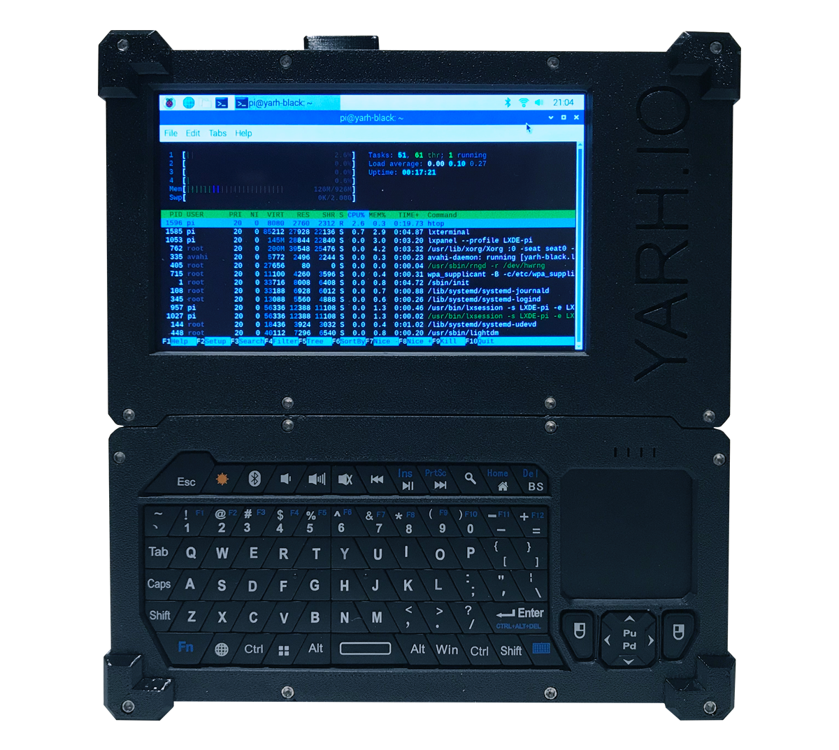
The display is a Kuman 5-inch resistive touch screen running at 800x480 over HDMI with an SPI-based ADS7846 touch controller. Resistive touch works with any stylus or gloved hand. The screen is large enough for terminal work, web browsing, and graphical applications without compromise. Touchscreen calibration is handled through xinput-calibrator and a persistent Xorg config file.
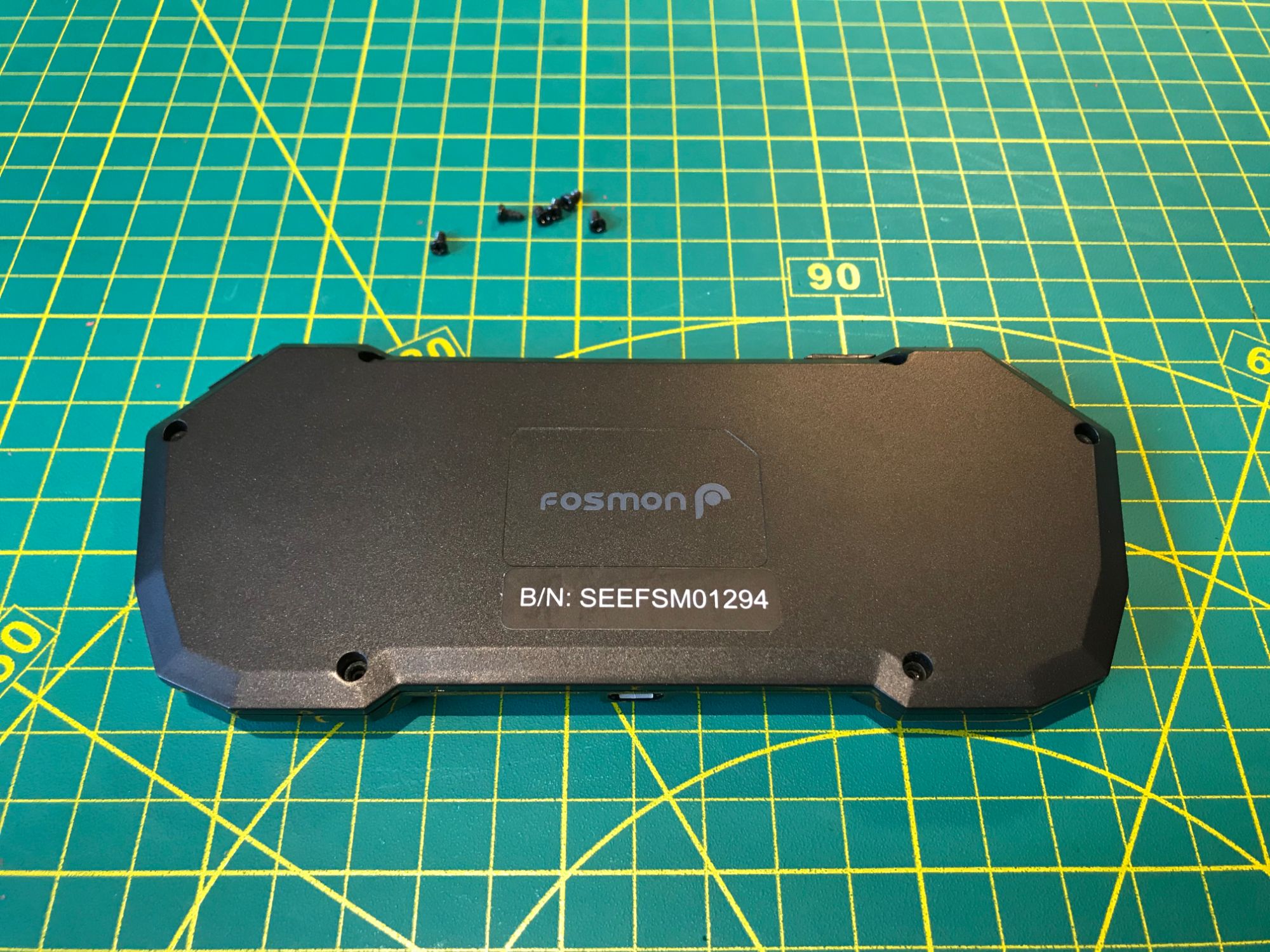
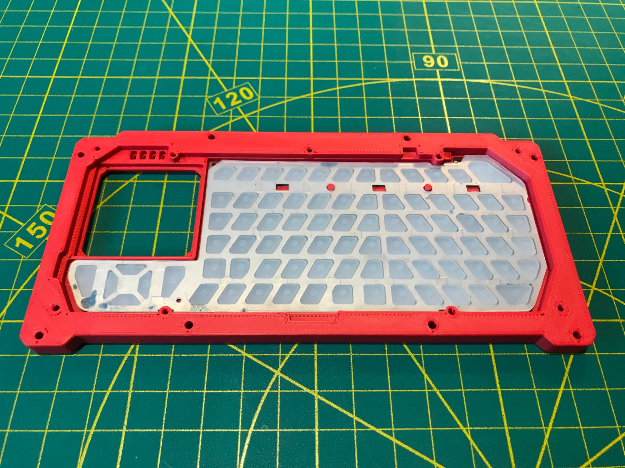
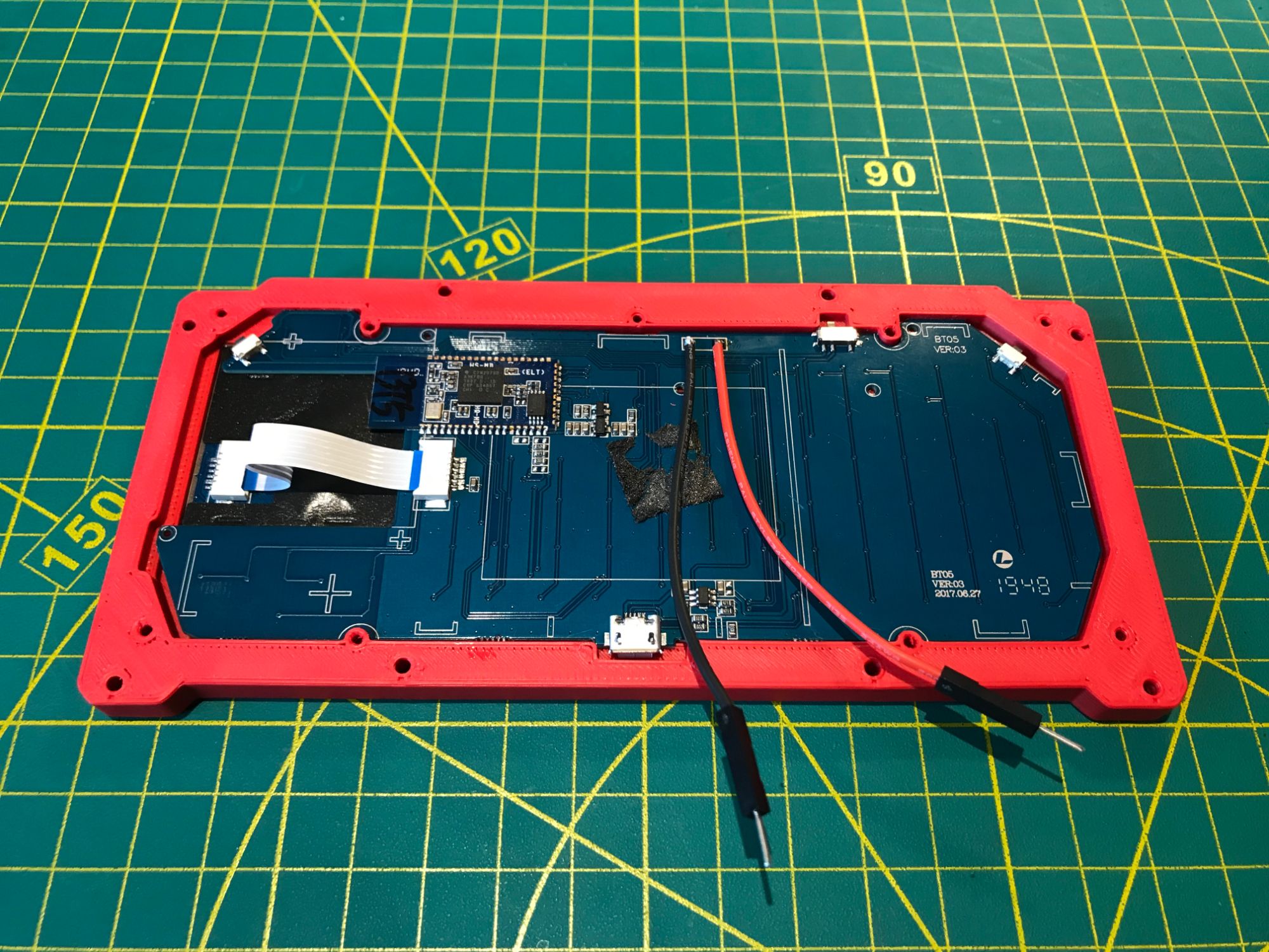
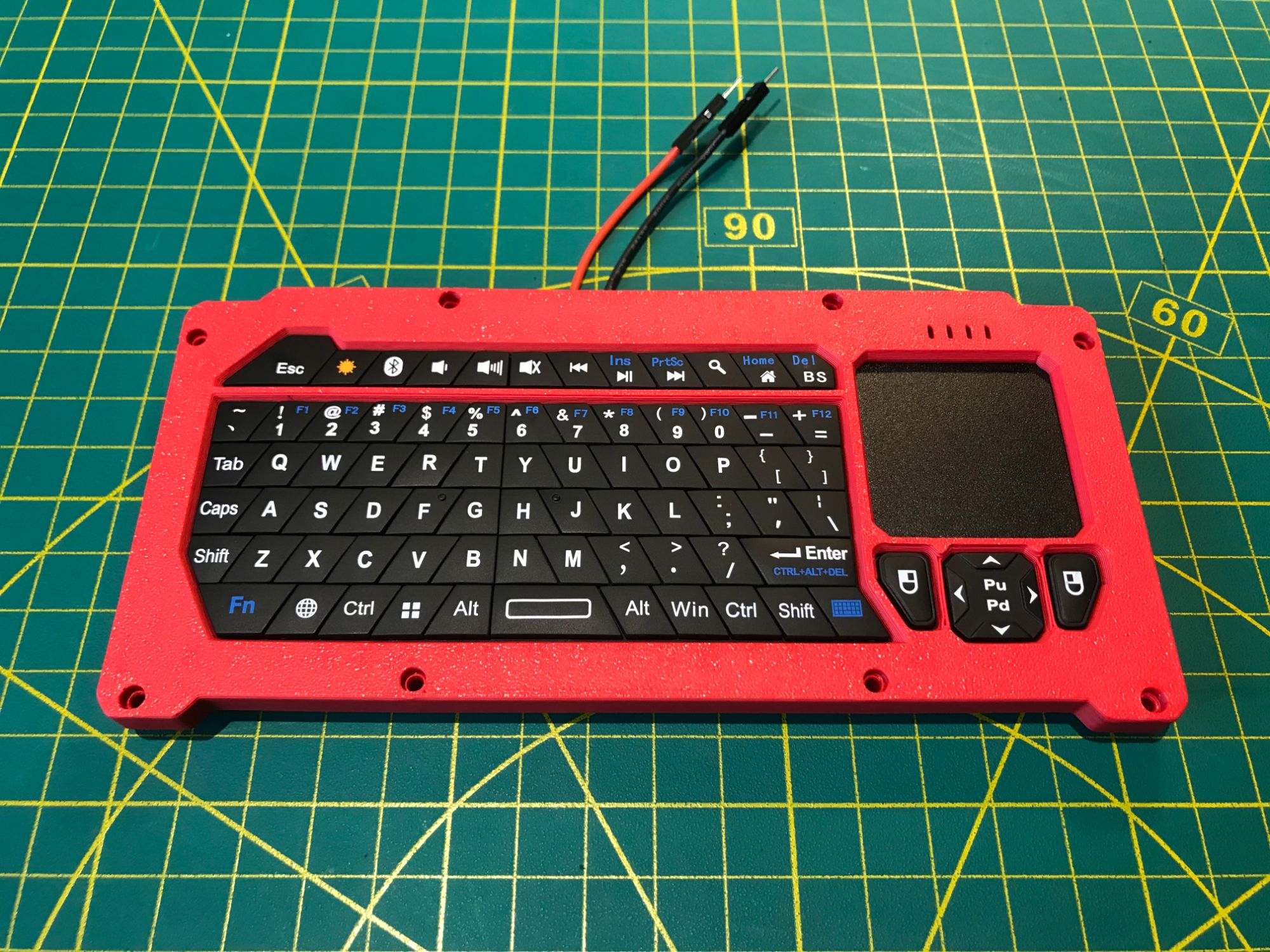
Input comes from a Fosmon portable Bluetooth keyboard with a built-in trackpad. The layout includes modifier keys for Vim, tmux, and Emacs workflows. The trackpad provides pointing capability for graphical applications and web browsing. Bluetooth pairing is done once through the system menu; on subsequent boots the keyboard reconnects automatically when you press Enter.
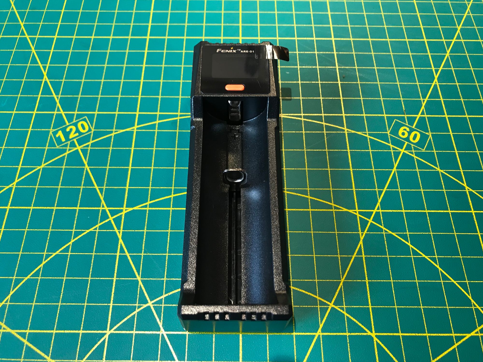
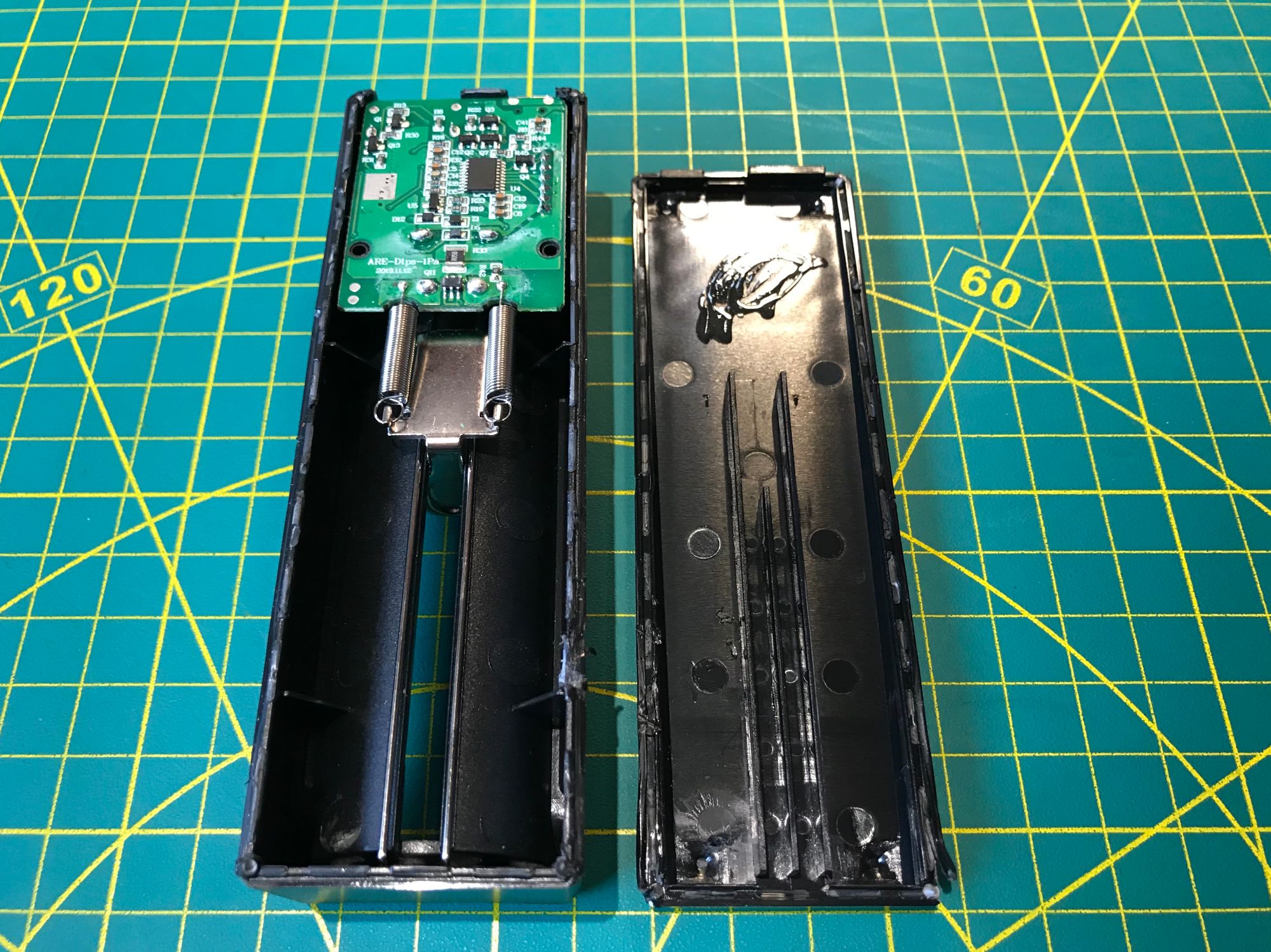
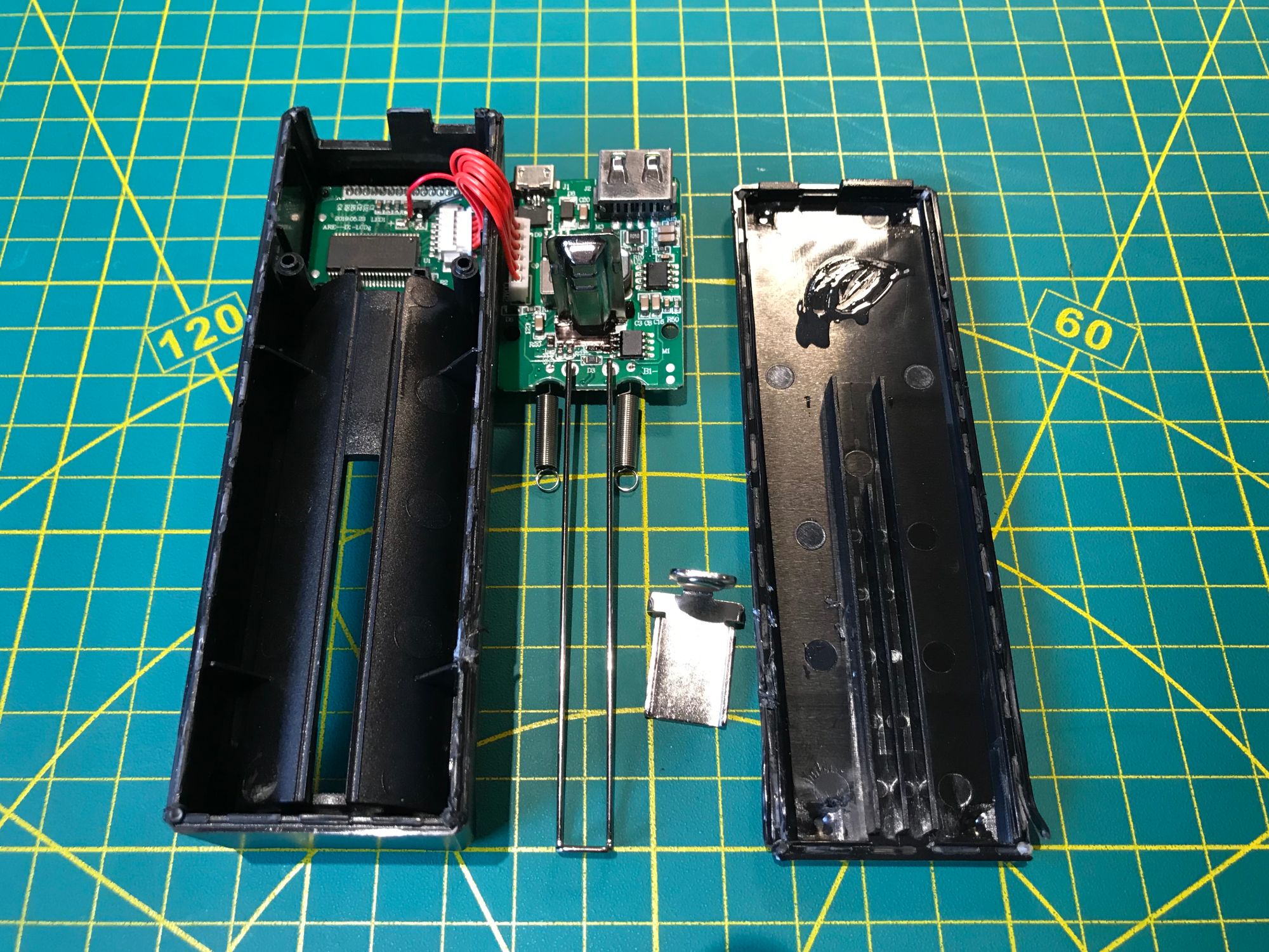
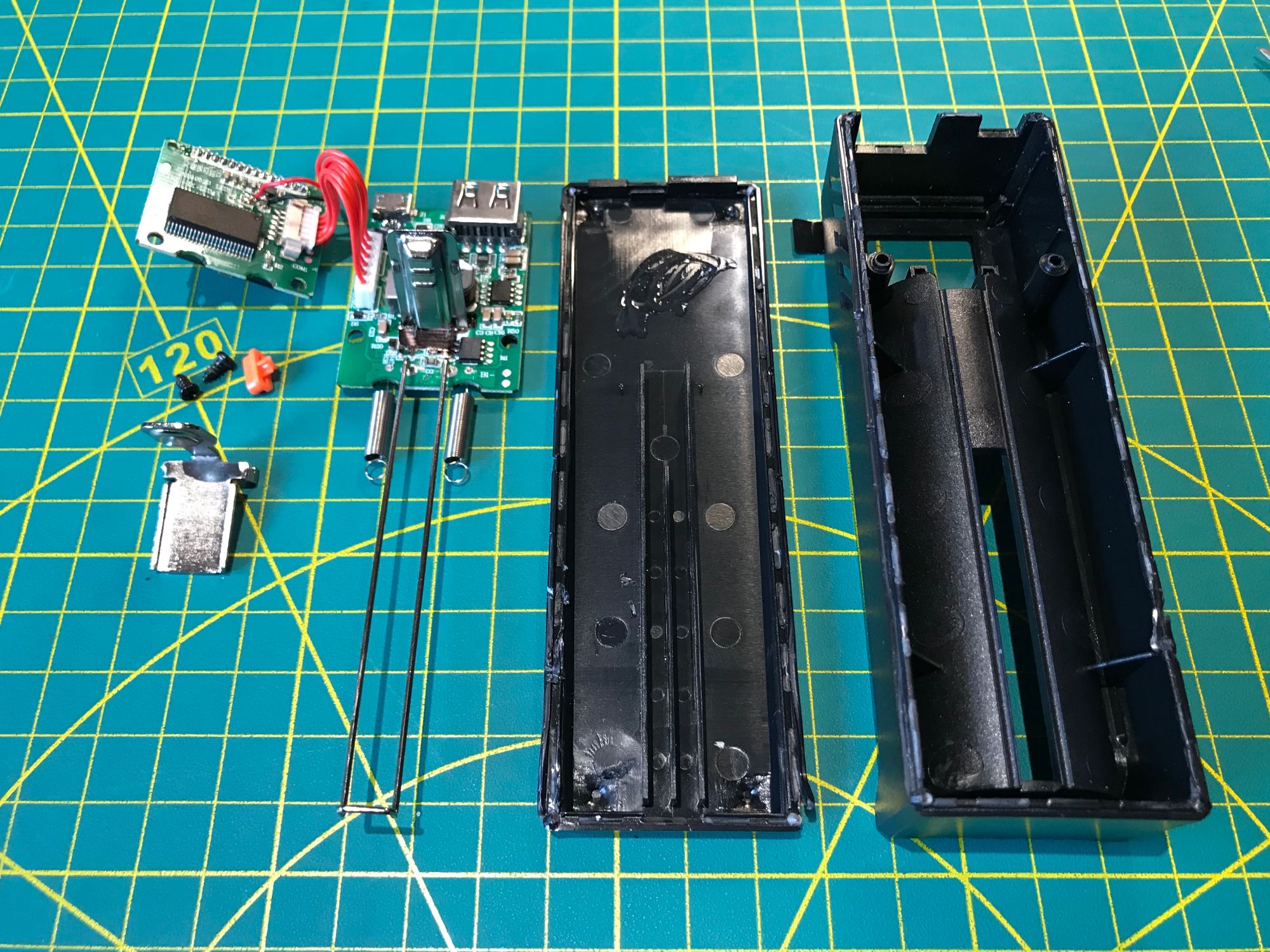
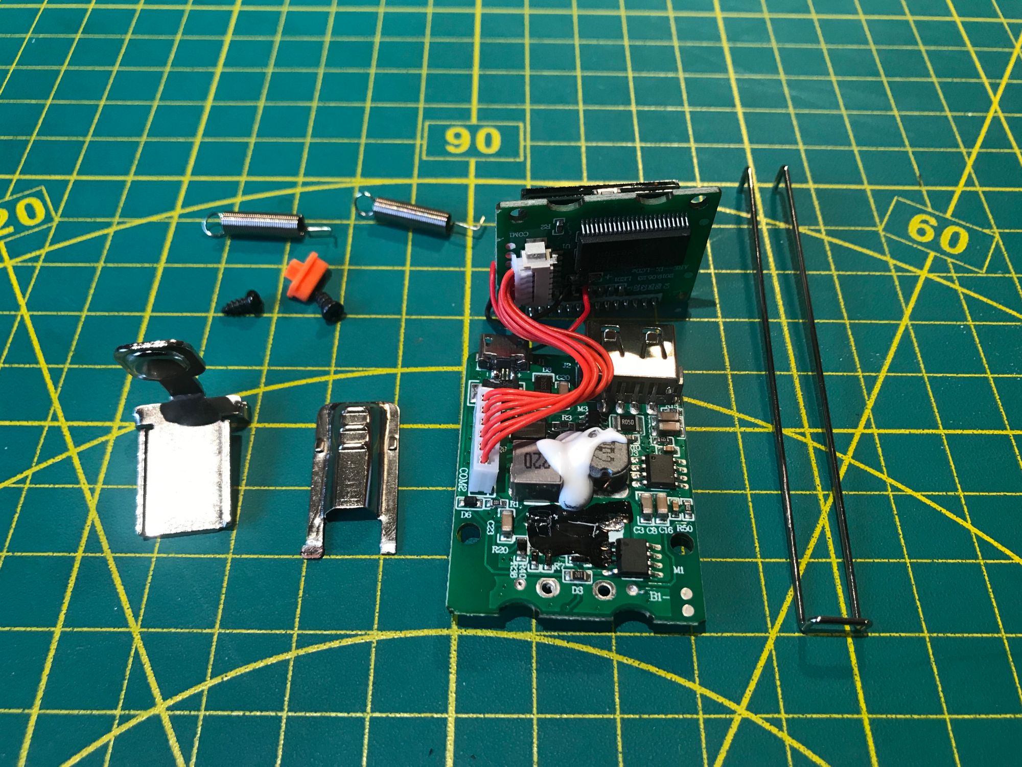
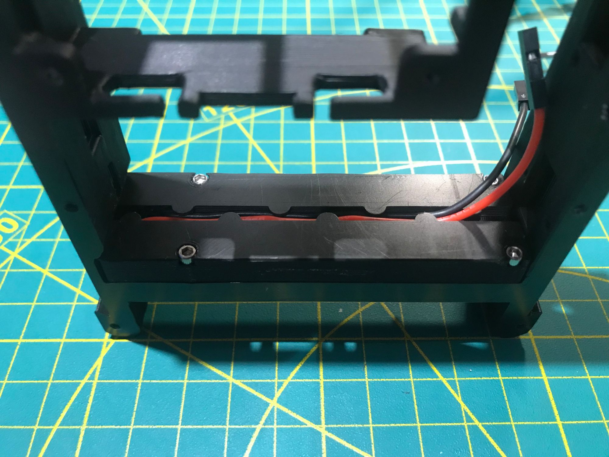
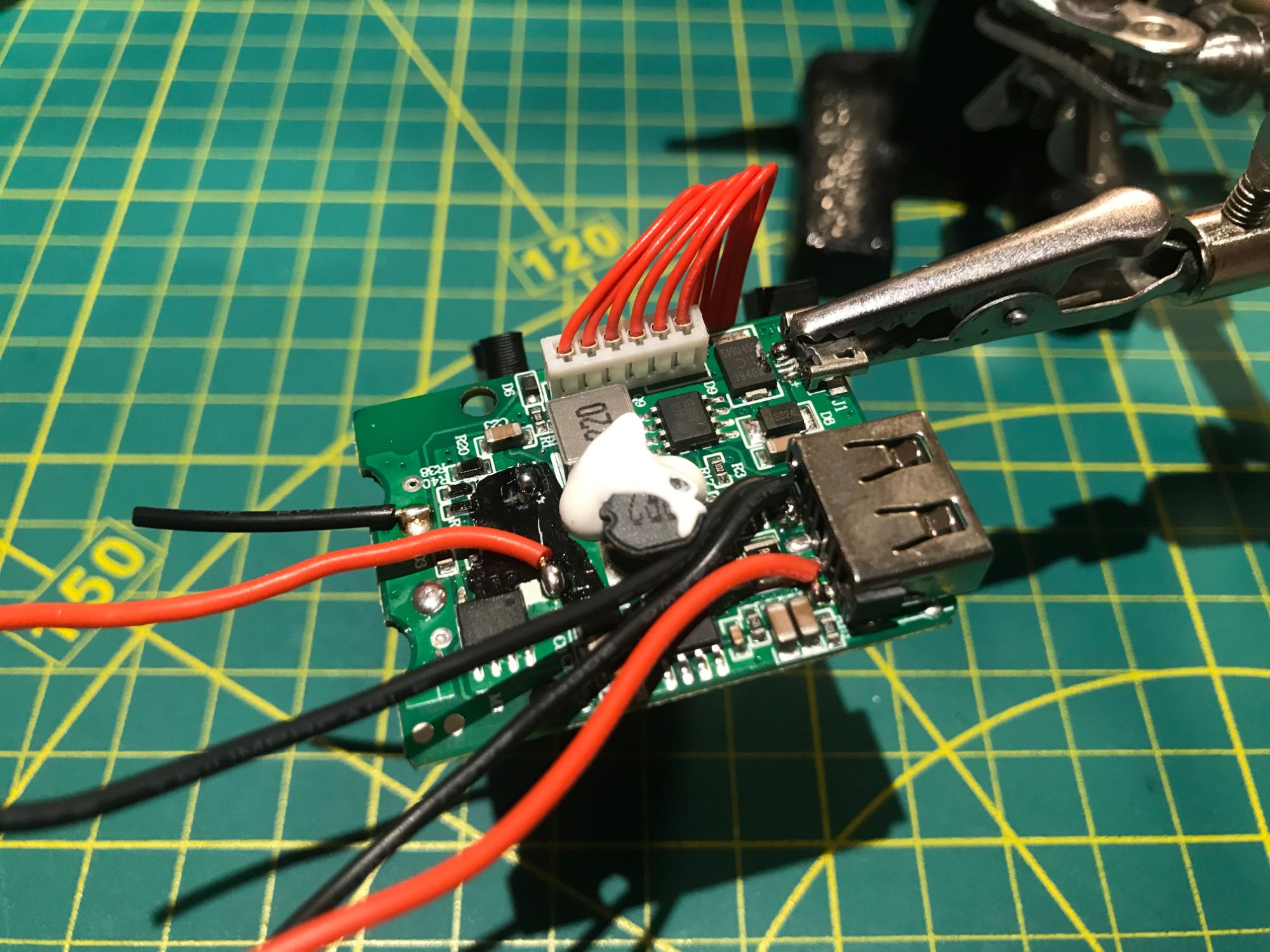
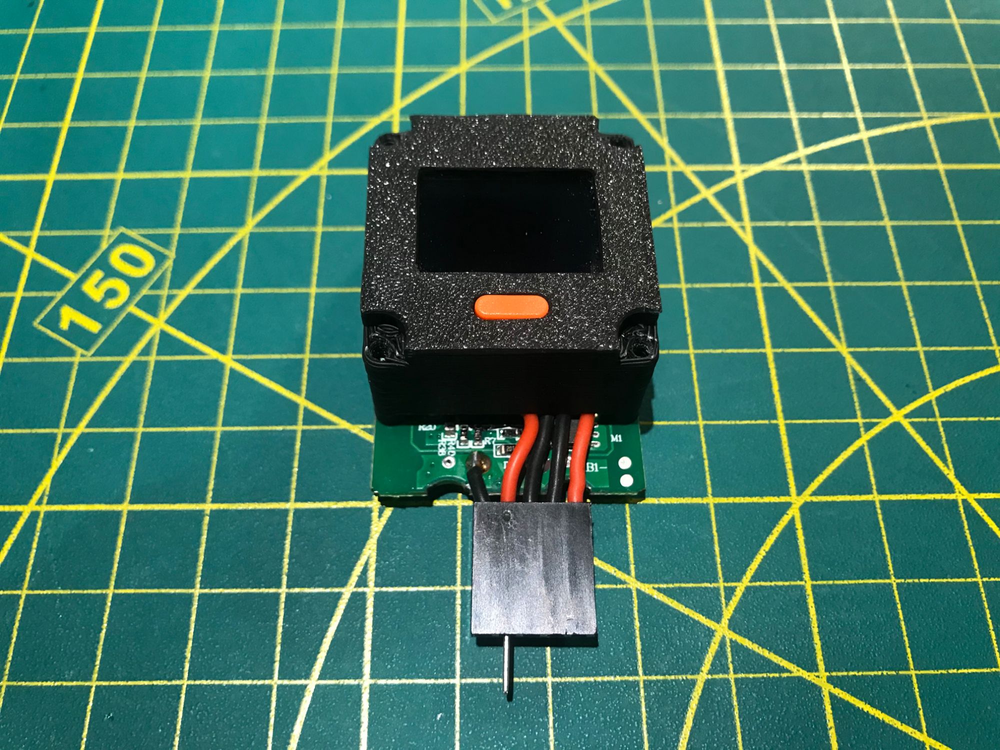
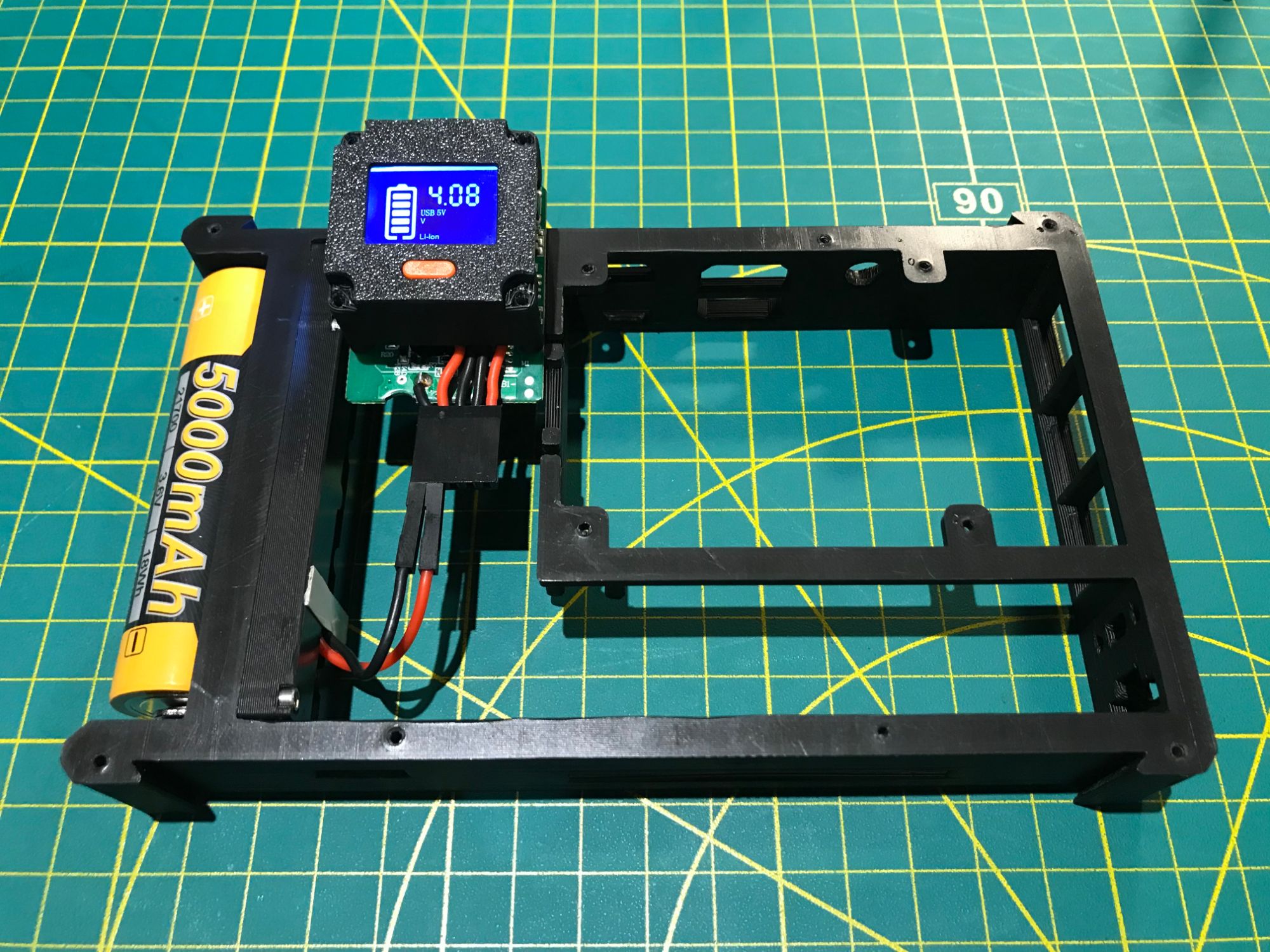
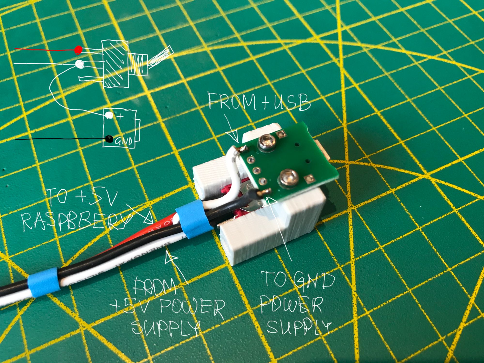
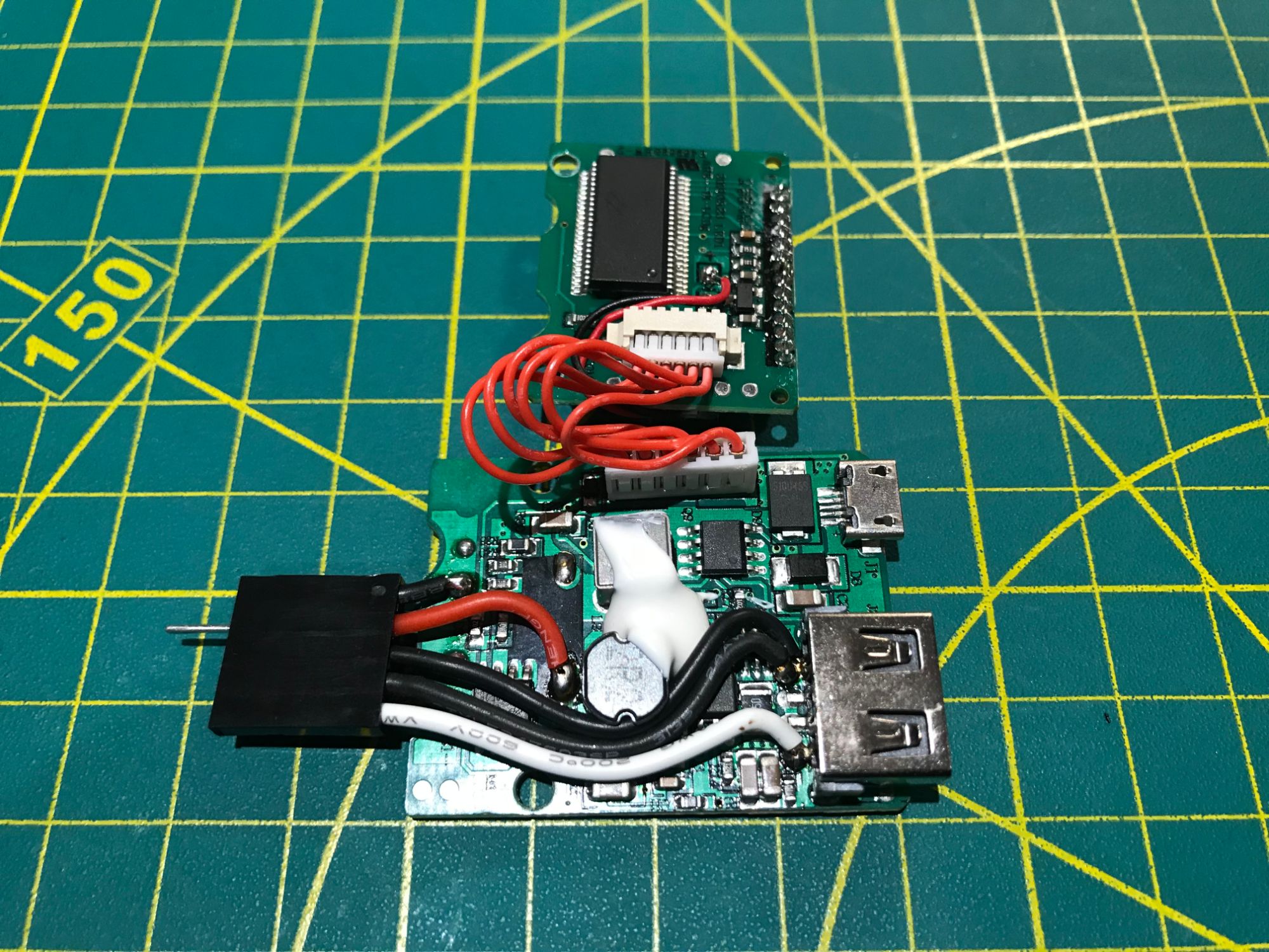
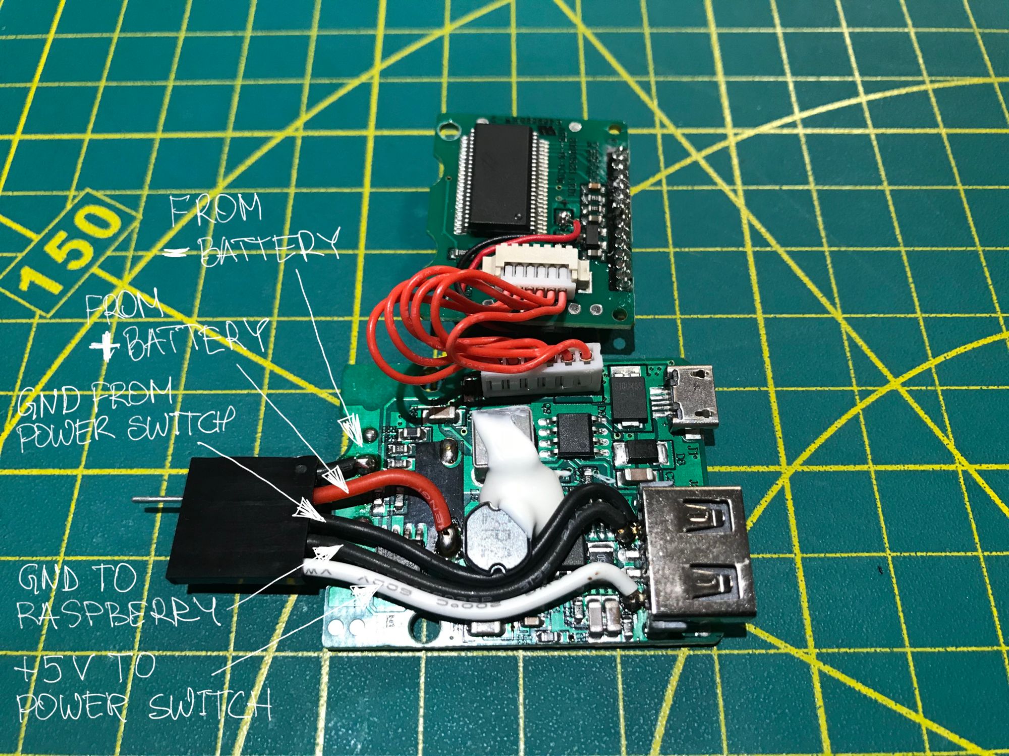
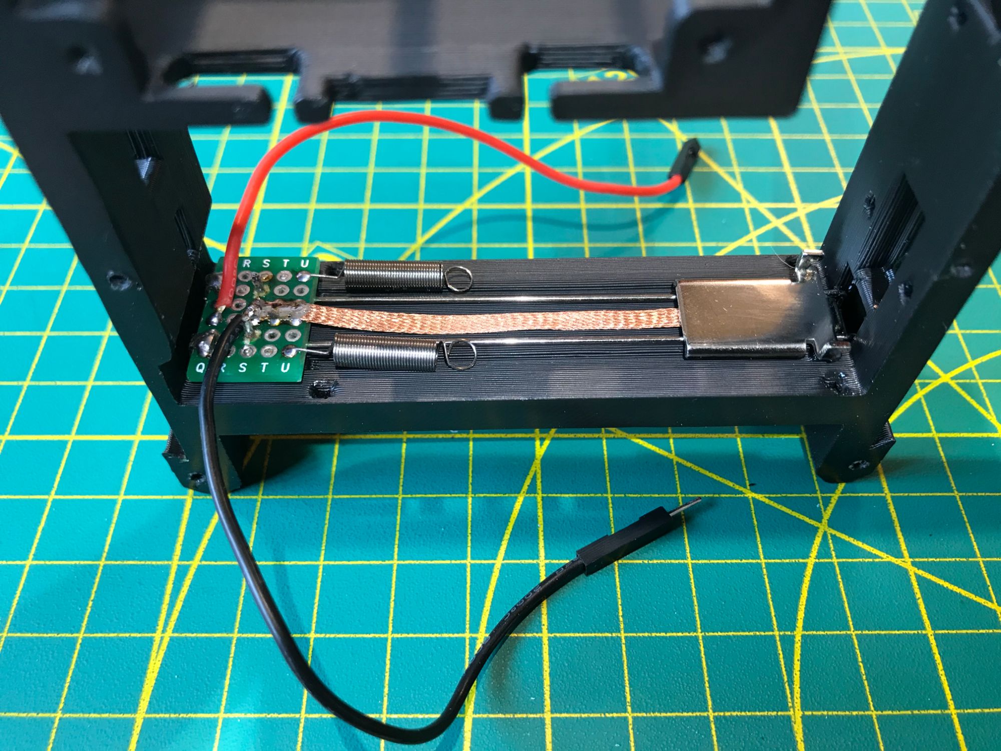
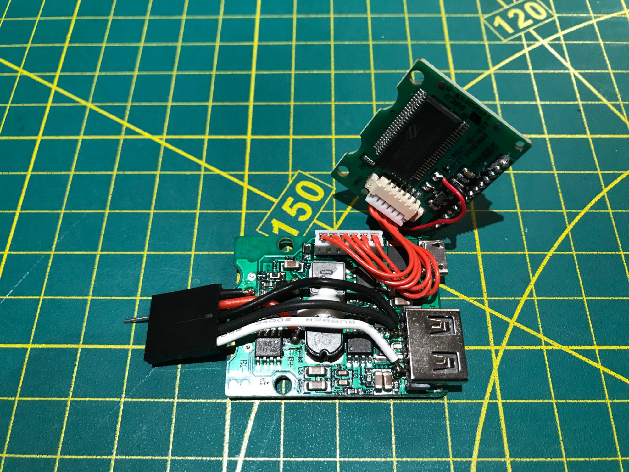
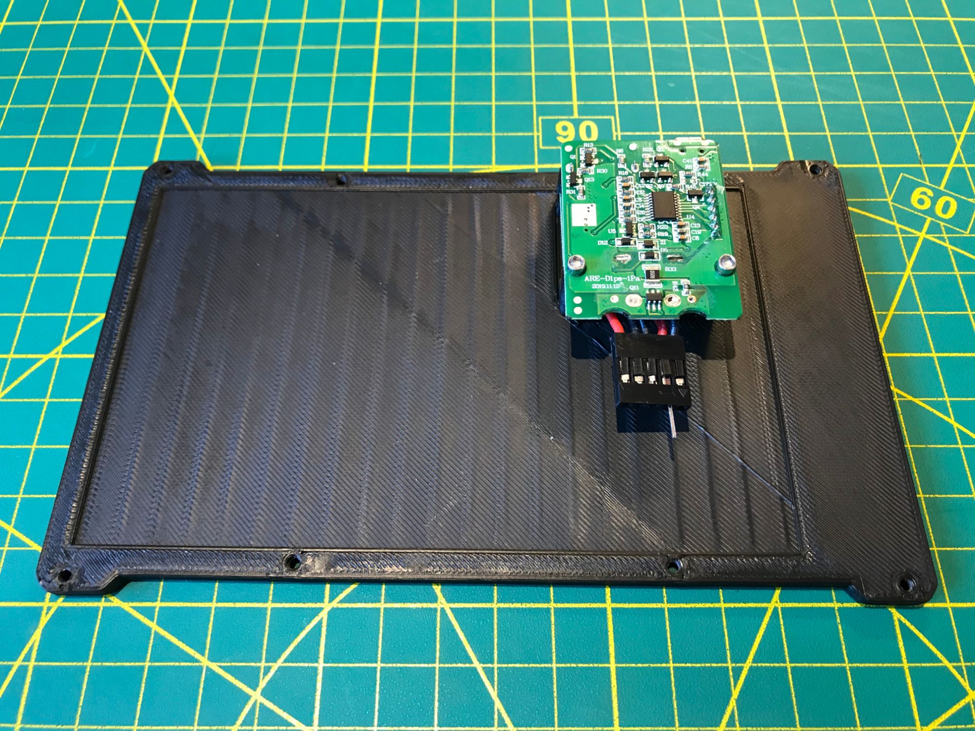
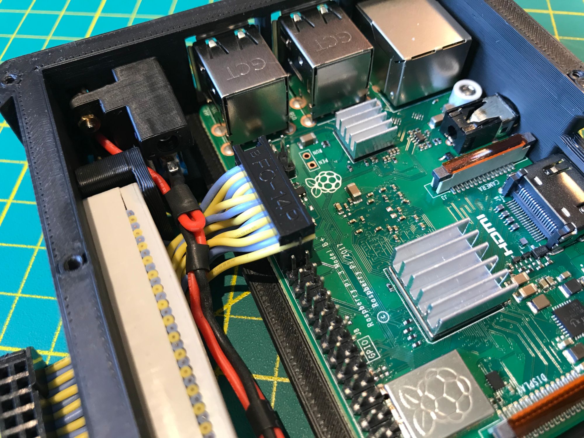
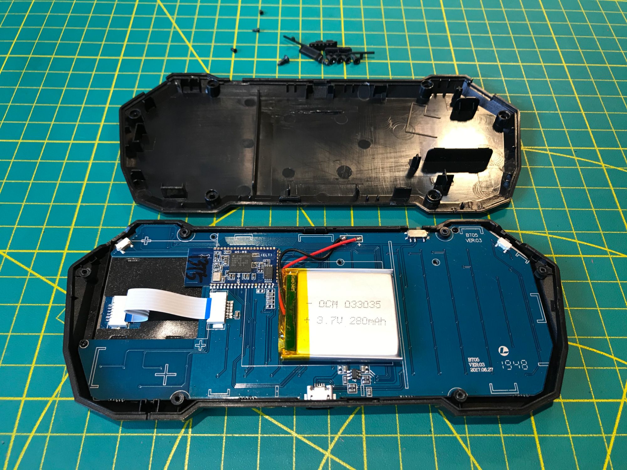
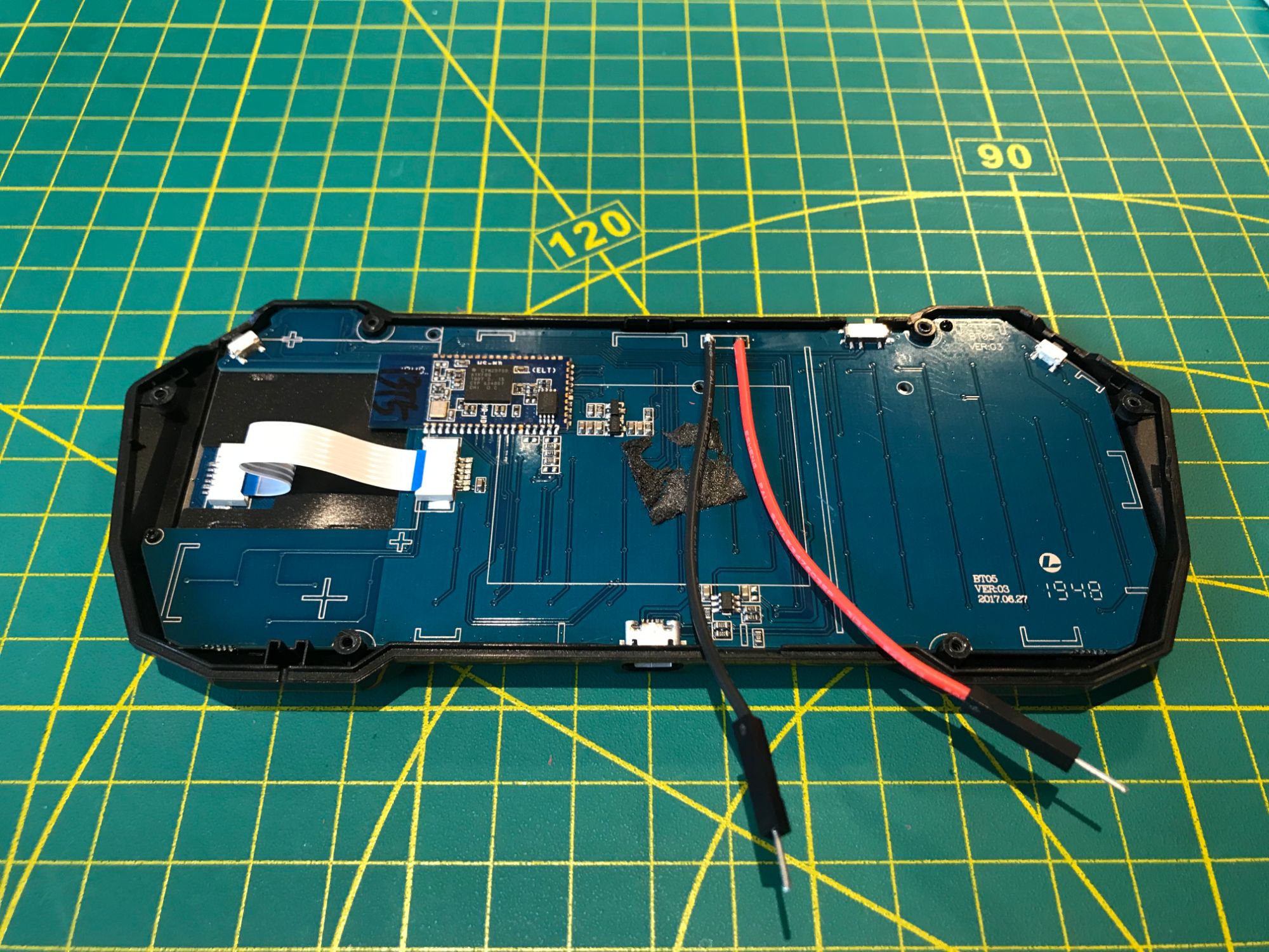
Power comes from a single removable Fenix ARB-L21-5000 lithium-ion cell — 5000 mAh in a standard 21700 form factor. The battery slides out for quick swaps in the field. Charging and 5V regulation use the internals of a Fenix ARE-D1 smart charger, mounted inside the housing. The Raspberry Pi 3B+ was chosen deliberately over the 4B for this build: lower power draw means longer runtime on a single cell, and the 3B+ provides more than enough compute for terminal work, scripting, and lightweight GUI tasks.
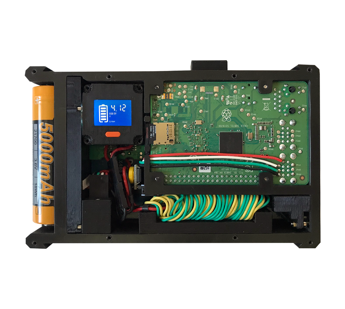
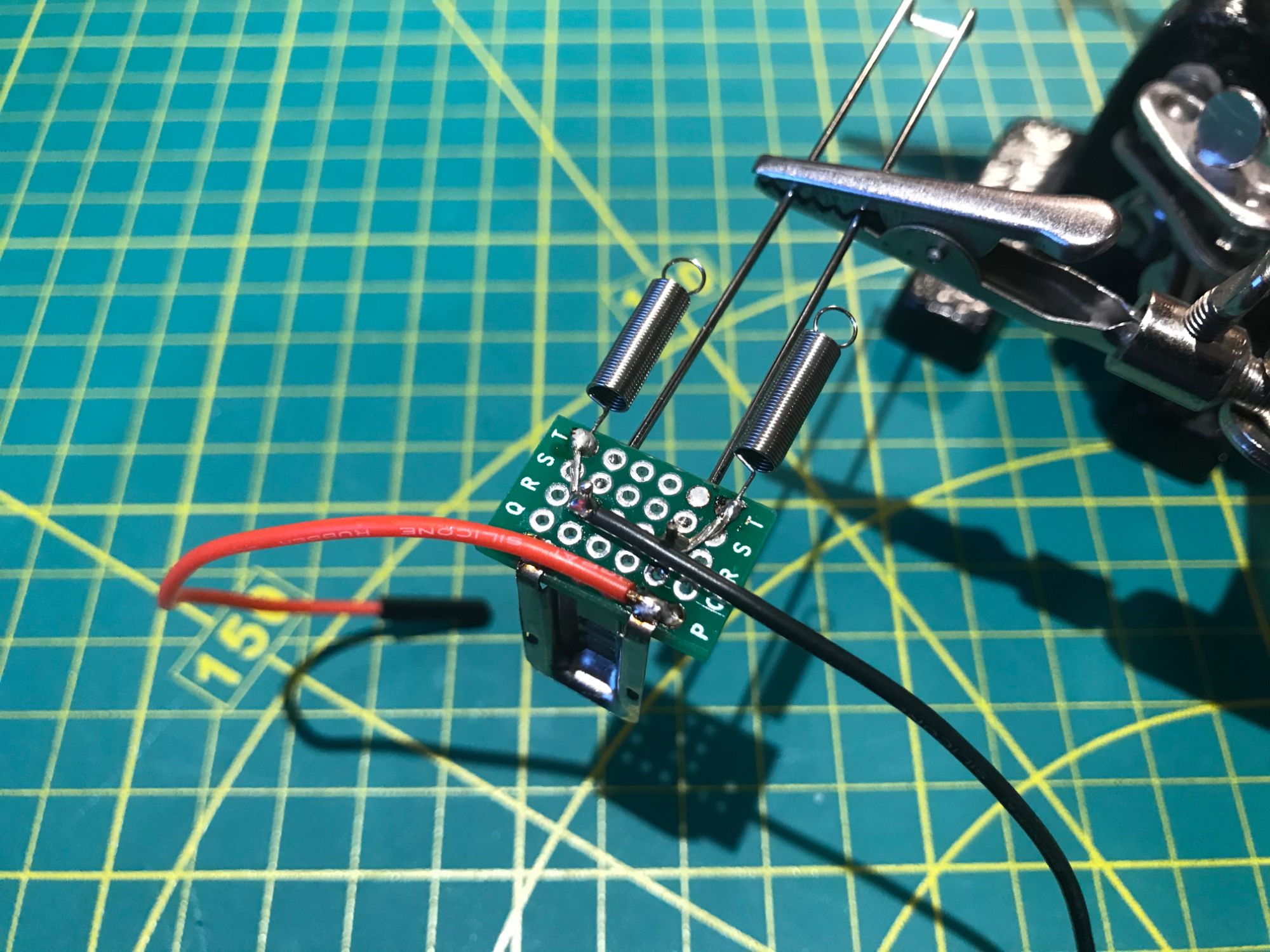
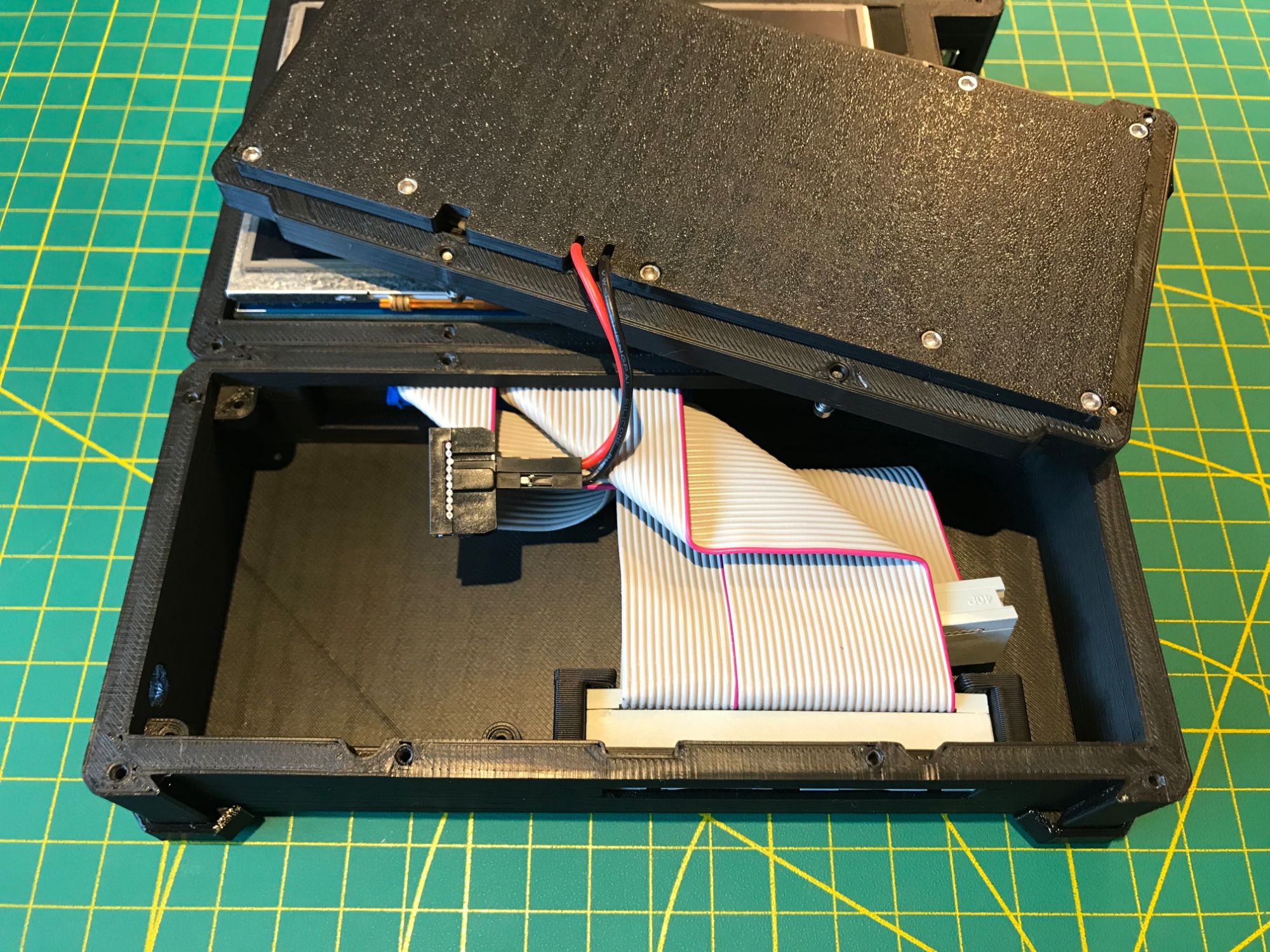
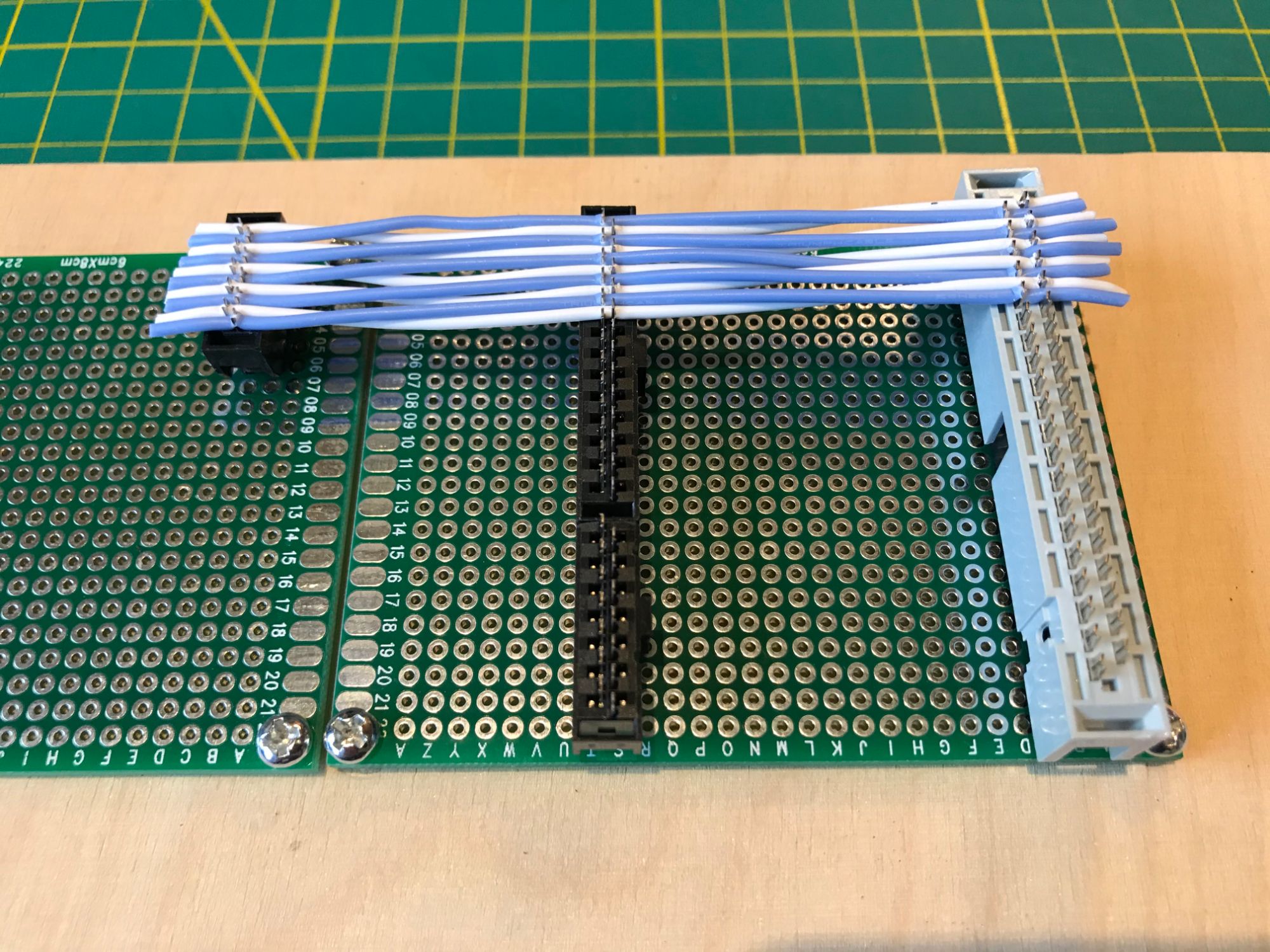
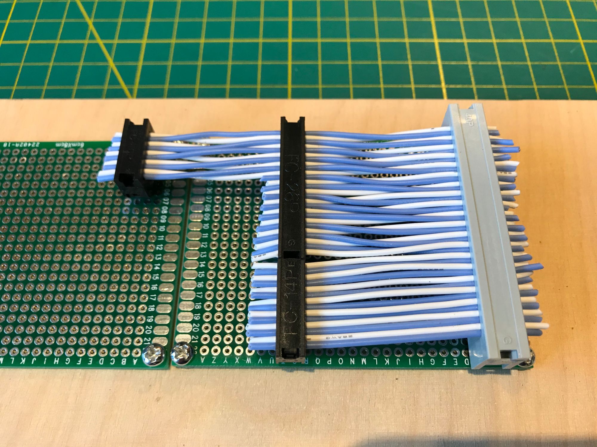
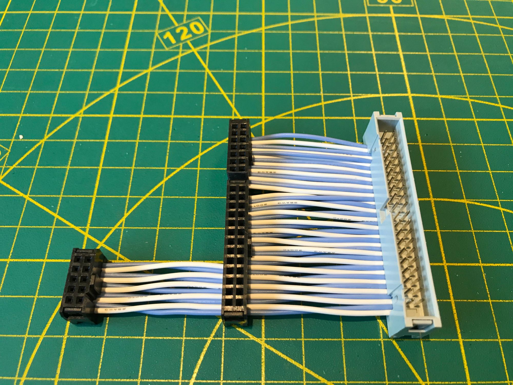
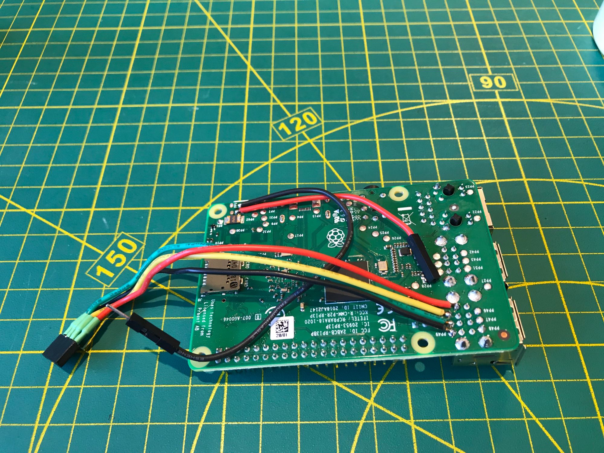
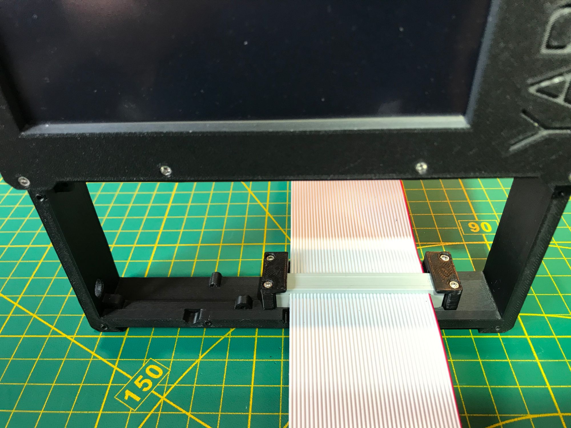
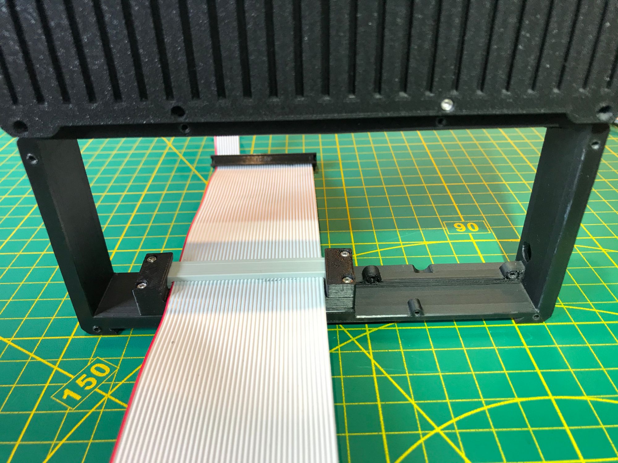
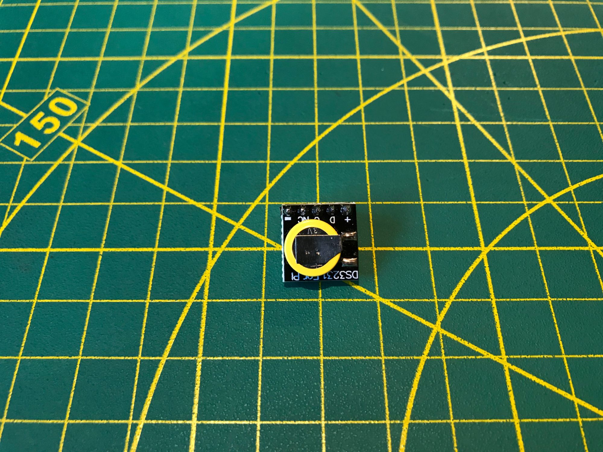
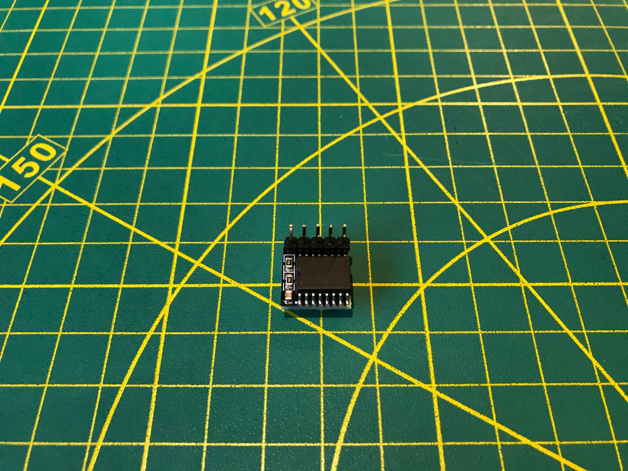
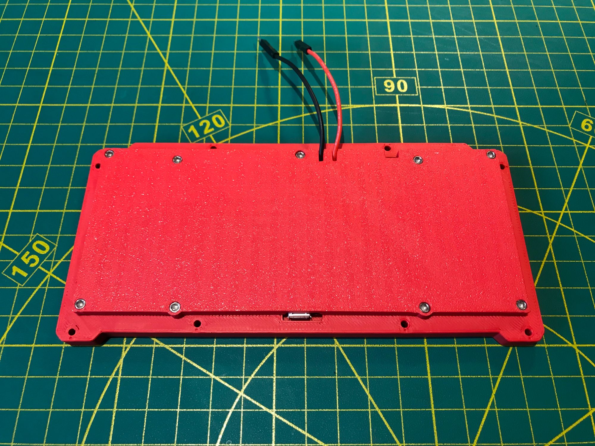
A DS3231 high-precision RTC module keeps time when the device is offline. It connects over I2C and is configured via a device tree overlay. The Raspberry Pi GPIO header is broken out to IDC connectors on the bottom of both the main module and the extension module, using 40-pin, 26-pin, 14-pin, and 10-pin female IDC sockets. This gives direct access to GPIO, I2C, SPI, and UART lines without opening the case. Any Raspberry Pi HAT or add-on board can be wired in through the extension module.

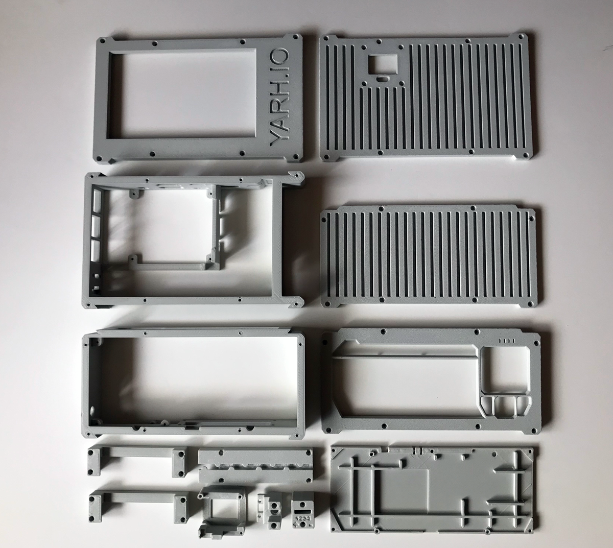
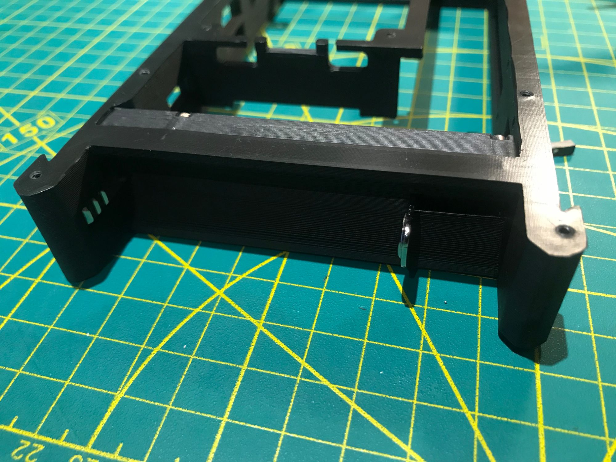
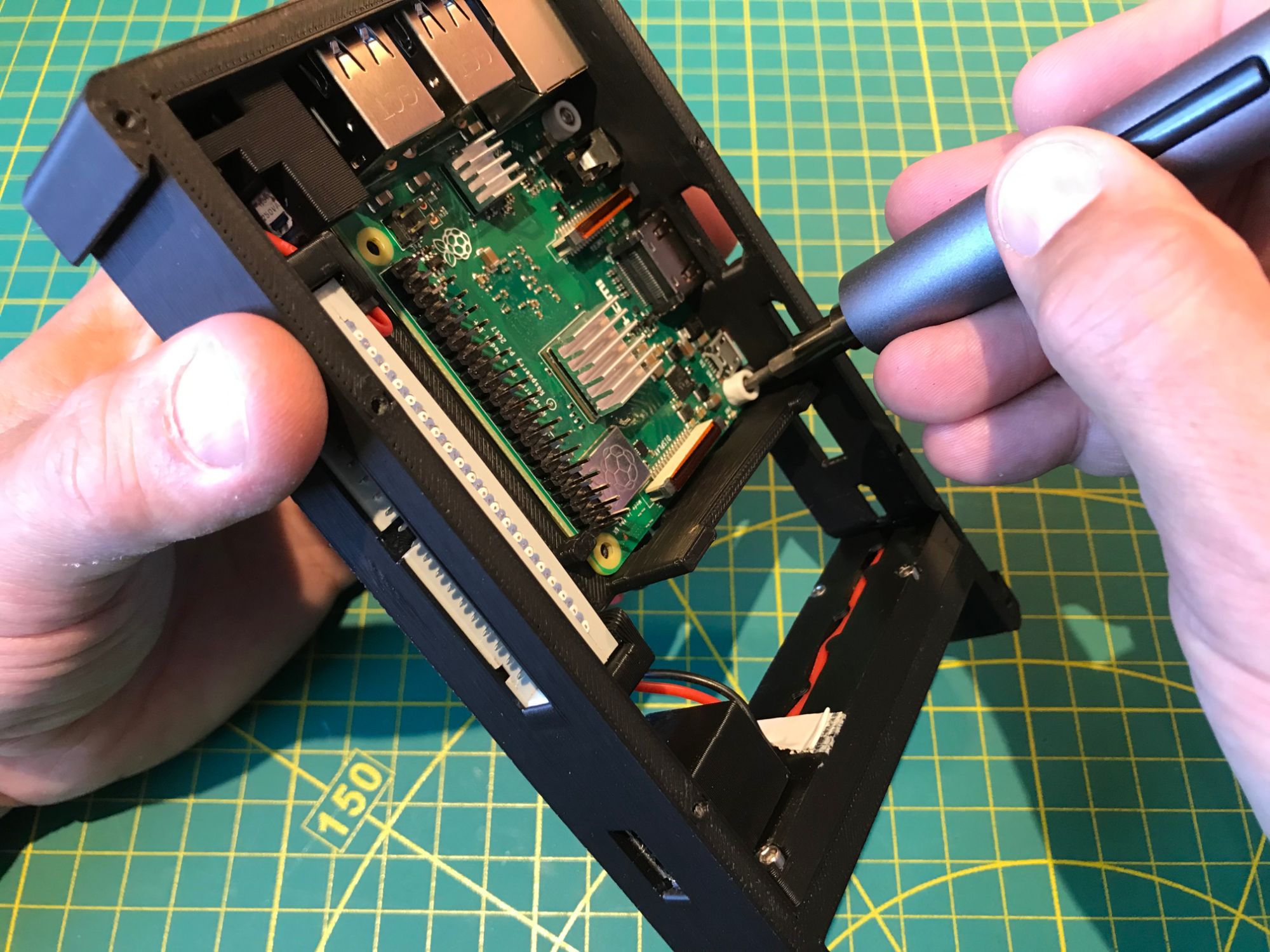
No snap-fit or glued joints. Every panel is fastened with #2-56 stainless steel socket cap screws — 1/4", 3/8", 1/2", and 3/4" lengths throughout. The device can be fully disassembled and reassembled with a single hex driver, and the screws tolerate repeated cycles without stripping. Rubber bumpers on the base protect surfaces and prevent sliding. All housing parts are 3D-printed in PLA, ABS, or ASA depending on the required strength and heat tolerance.
Parts
| Part | Source |
|---|---|
| Raspberry PI 3B+ | Raspberry Pi |
| Kuman 5'' Resistive Touch Screen 800x480 HDMI TFT Display | Amazon |
| Fosmon Mini Bluetooth Keyboard | Amazon |
| Fenix ARE-D1 is a single channel smart charger | Fenix Tactical |
| Fenix ARB-L21-5000 V2.0 Li-ion rechargeable battery | Amazon |
| High Precision Real Time Clock Module | Amazon |
| 40 Pin IDC Socket Connector Male X 3 | Amazon |
| 40 Pin IDC Socket Connector Female | Amazon |
| 26 Pin IDC Socket Connector Female | Amazon |
| 14 Pin IDC Socket Connector Female | Amazon |
| 10 Pin IDC Socket Connector Female X 2 | Amazon |
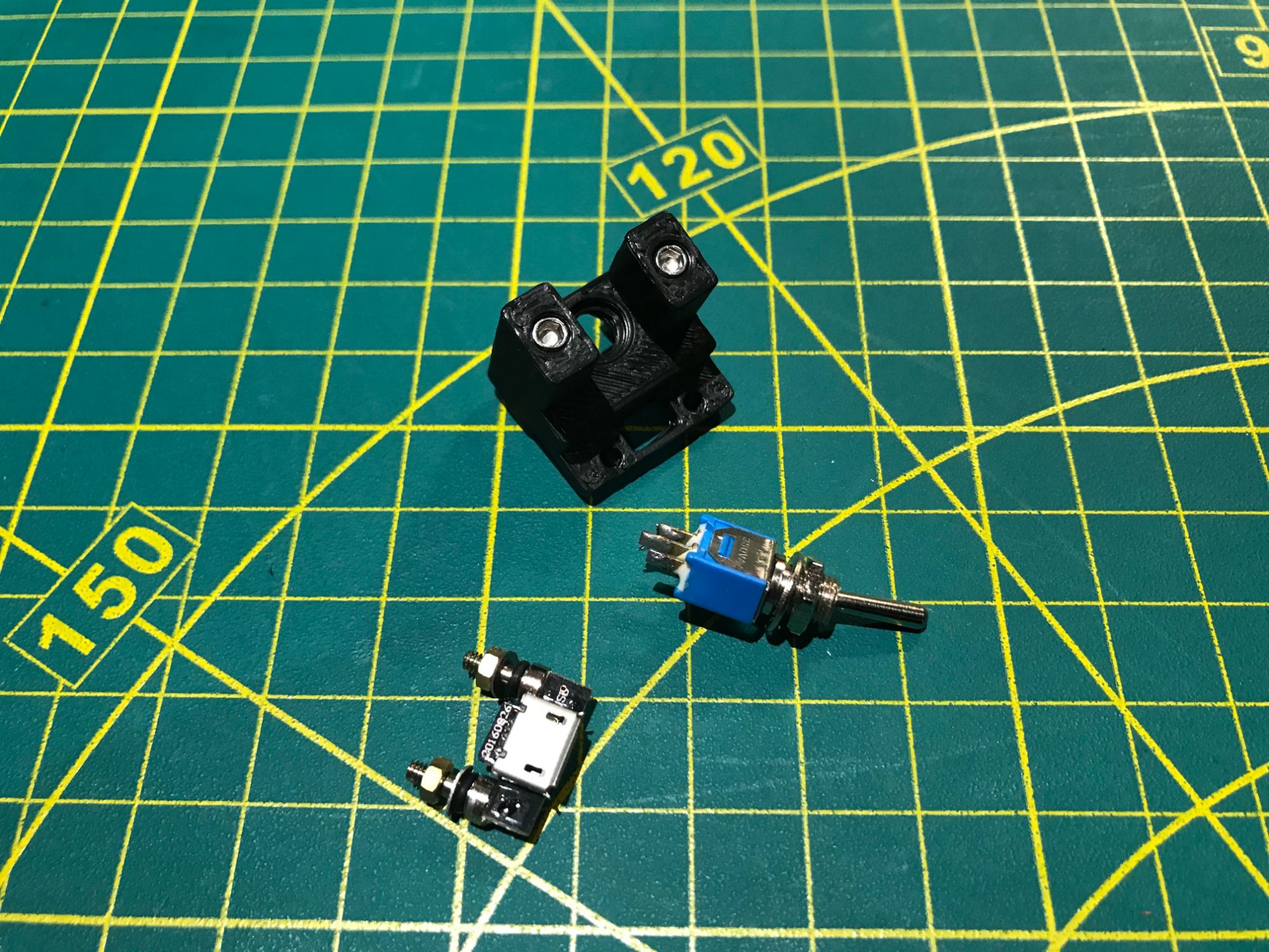
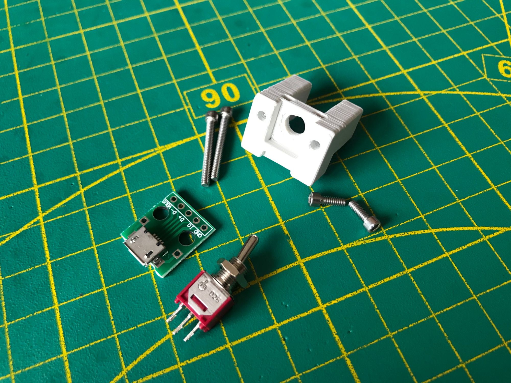
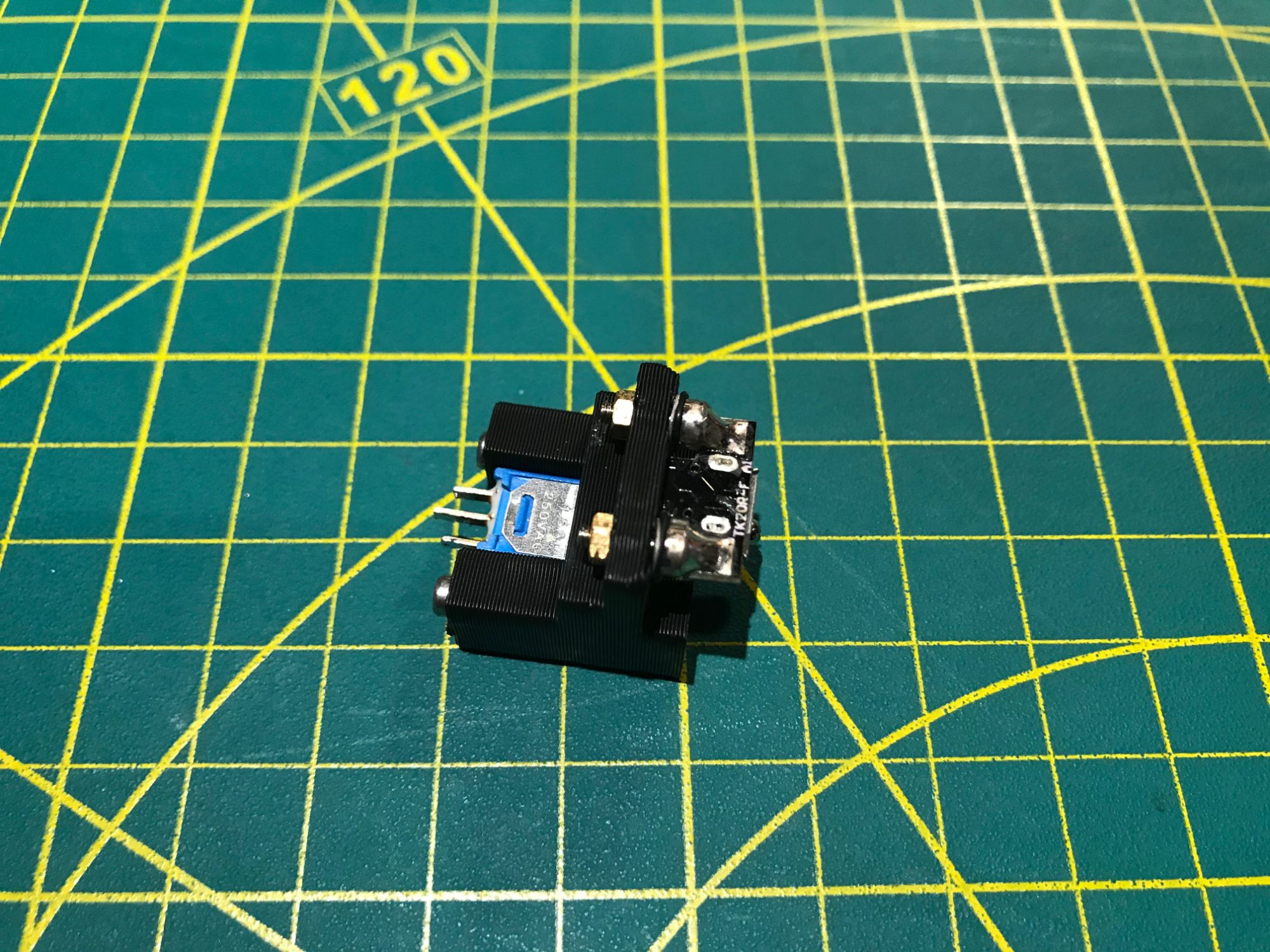
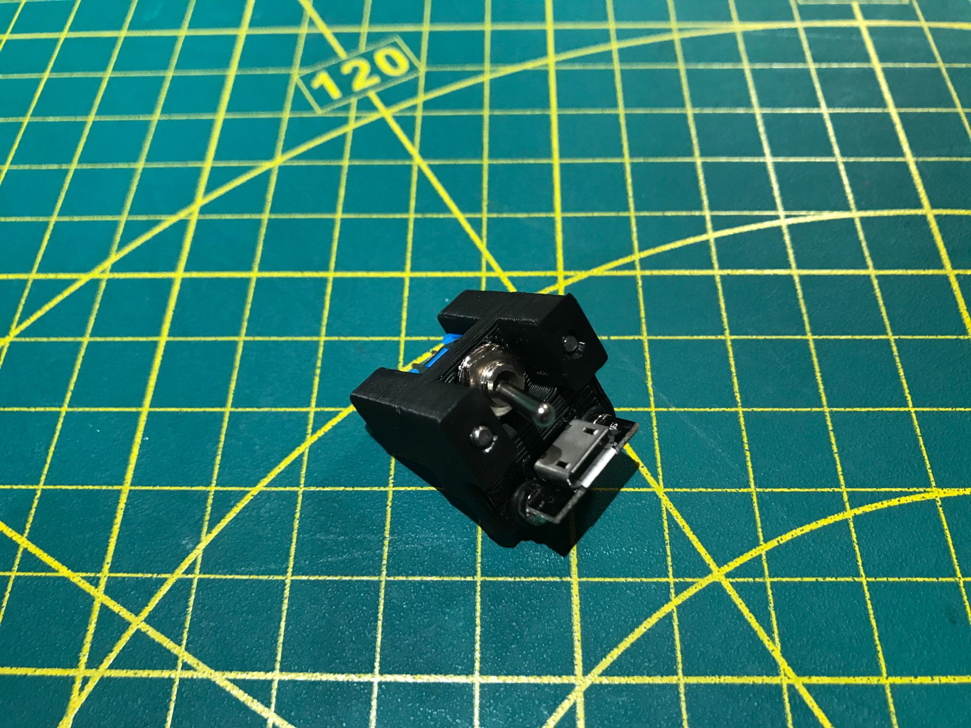
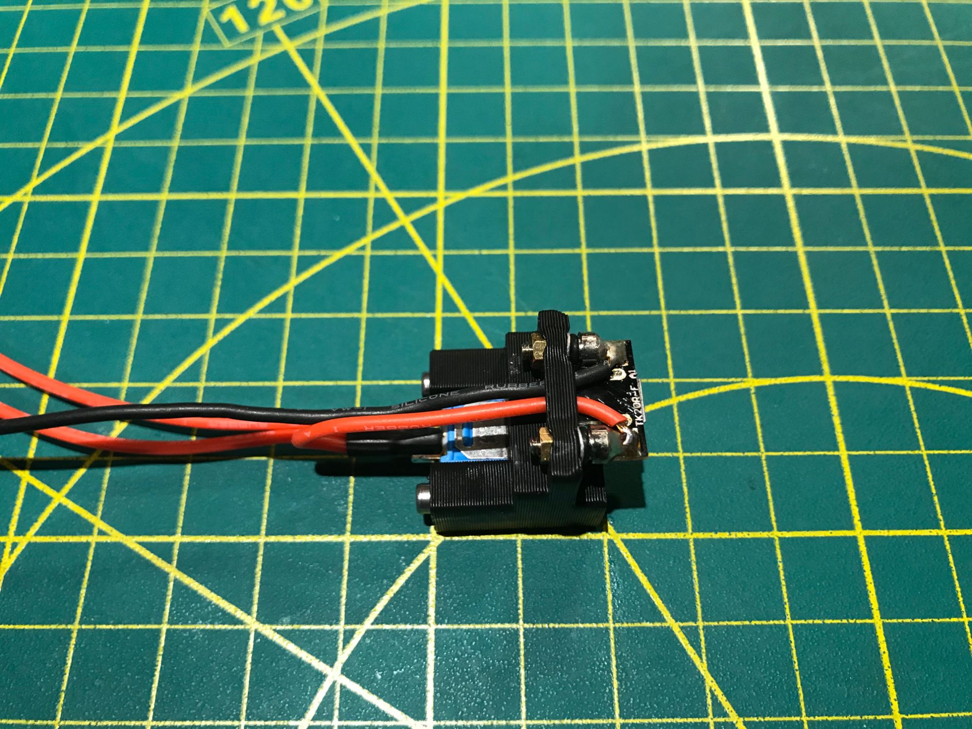
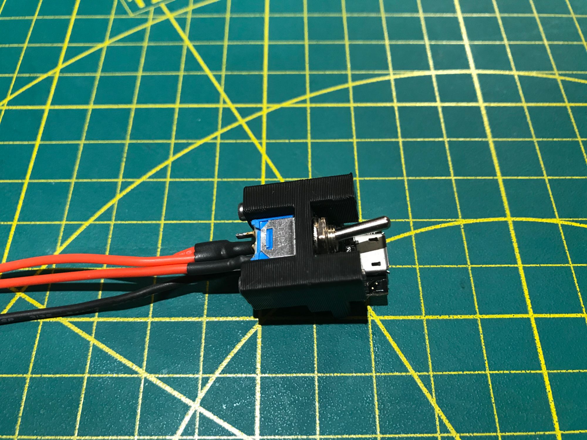
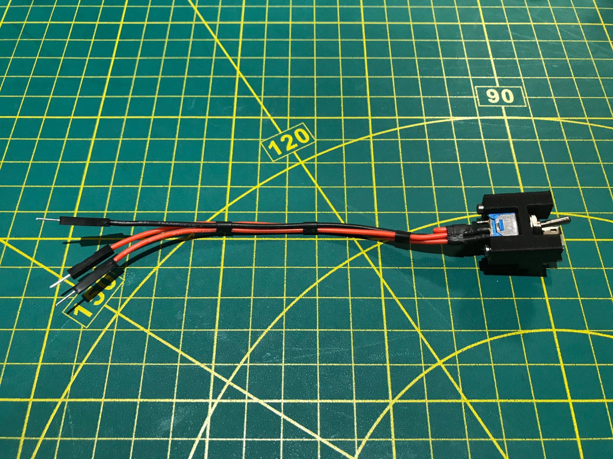
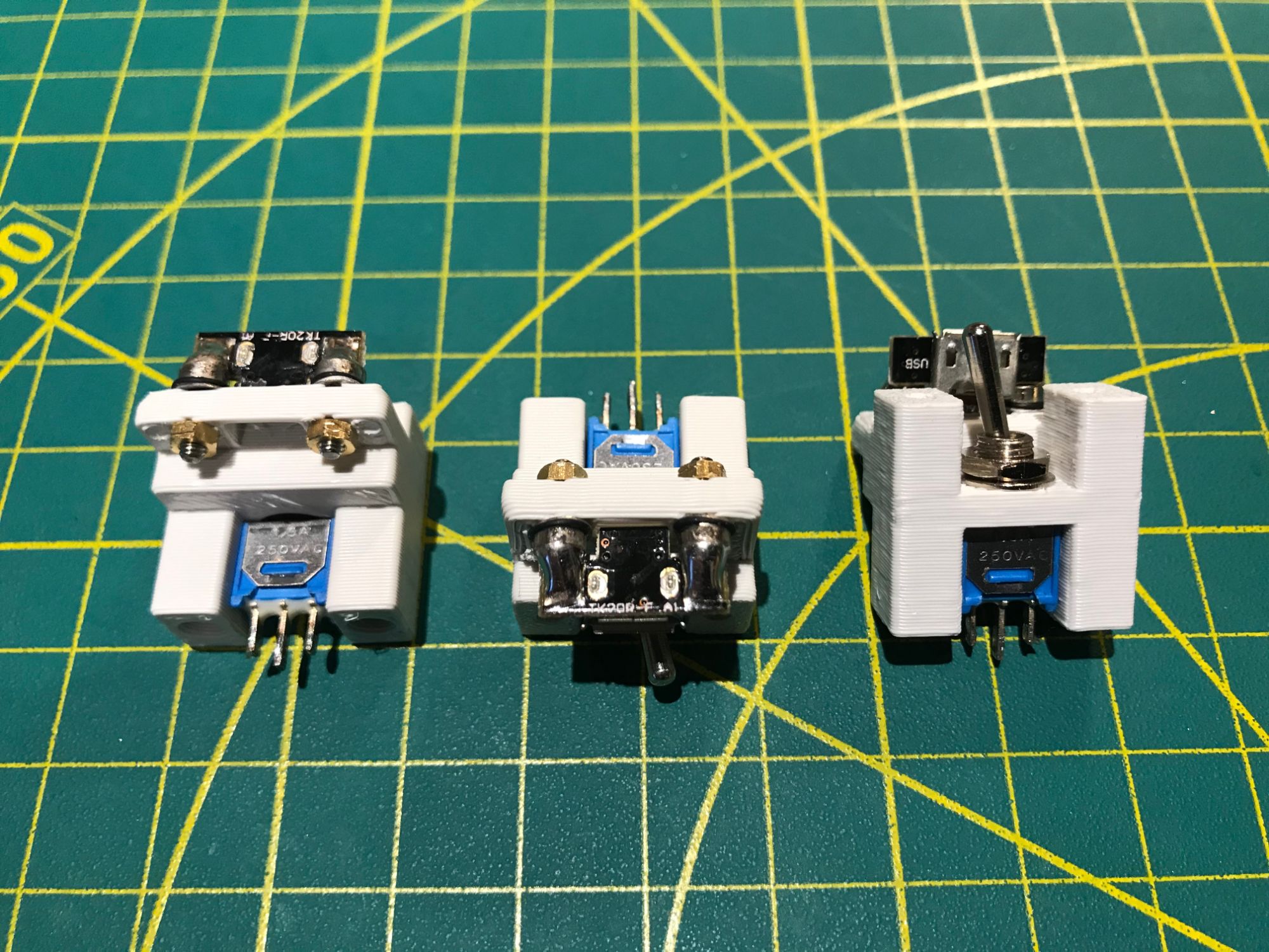
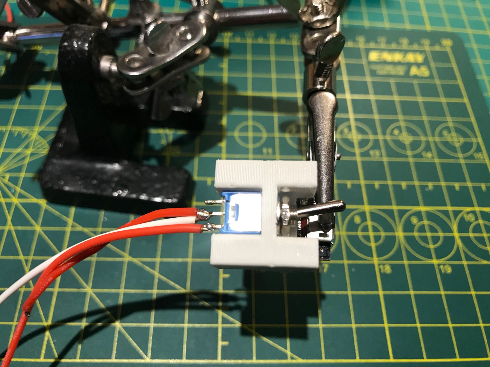
| 2 Position 3 Pin SPDT Mini Micro Toggle Switch | Amazon |
| Micro USB Connector Adapter | Amazon |
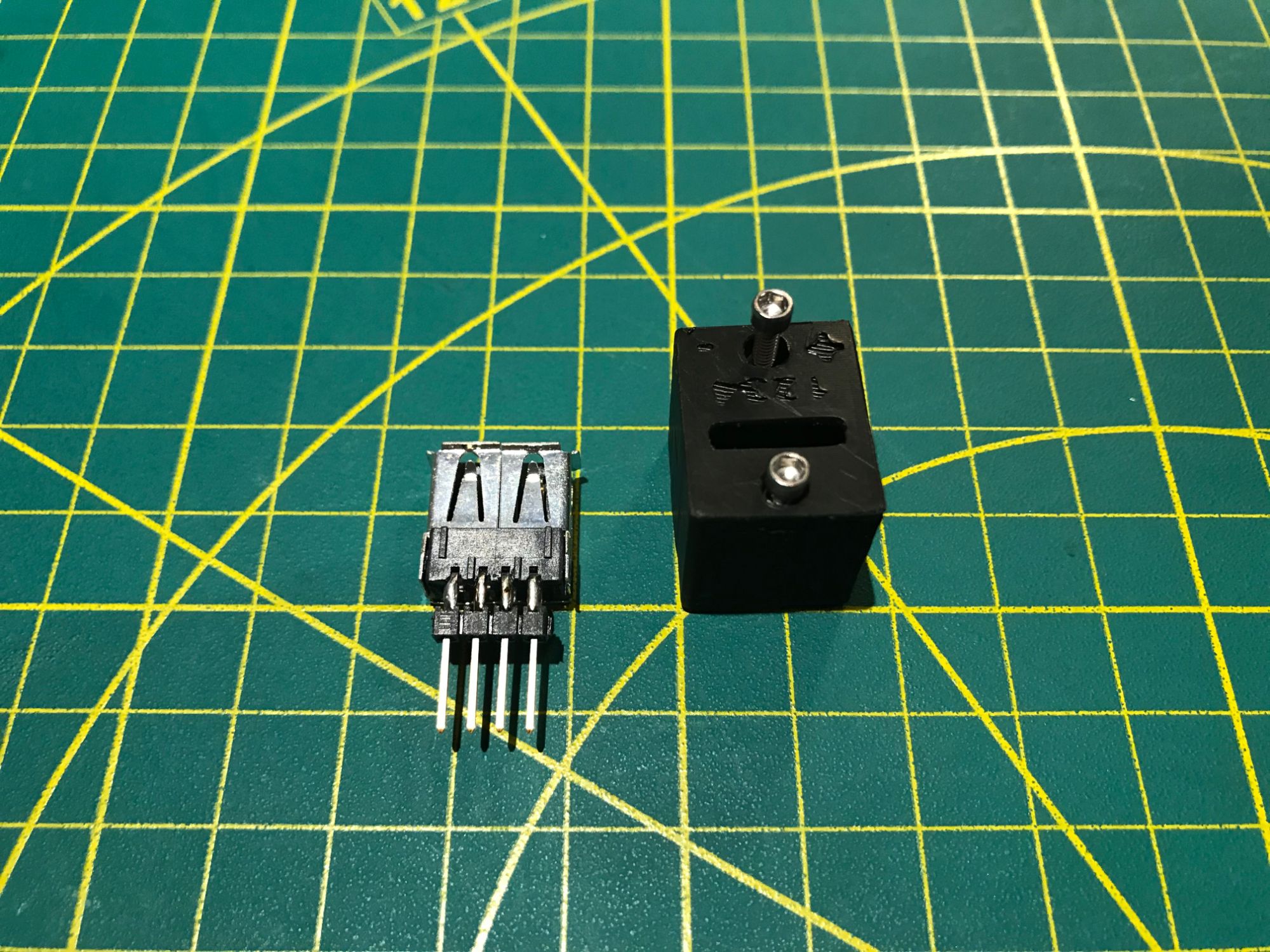
| USB 2.0 Type A Male Socket Connector | Amazon |
| Flexible Silicone Rubber Wire 24AWG, 28AWG | Amazon |
| Jumper Wire Pins, Male and Female | Amazon |
| #2-56 Socket Cap Screw, Stainless Steel. 1/4'' x 33, 3/8'' x 20, 1/2'' x 8, 3/4'' x 4. | Trimcraft Aviation RC |
Gallery


System & Software
Software packages
sudo apt install tmux vim mc xserver-xorg-input-evdev xinput-calibrator i2c-tools -y/boot/config.txt
# Enable internal audio (loads snd_bcm2835)
dtparam=audio=on
# Configure HDMI
disable_overscan=1
hdmi_drive=1
hdmi_force_hotplug=1
hdmi_ignore_edid=0xa5000080
hdmi_group=2
hdmi_mode=1
hdmi_mode=87
# Enable 800x480 Mode
hdmi_cvt 800 480 60 6 0 0 0
# Enable Touchscreen
dtoverlay=ads7846,cs=1,penirq=25,penirq_pull=2,speed=50000,keep_vref_on=0,swapxy=0,pmax=255,xohms=150,xmin=200,xmax=3900,ymin=200,ymax=3900
# Enable RTC
dtparam=i2c_arm=on
dtoverlay=i2c-rtc,ds3231
/usr/share/X11/xorg.conf.d/10-evdev.conf
sudo cp -rf /usr/share/X11/xorg.conf.d/10-evdev.conf /usr/share/X11/xorg.conf.d/45-evdev.conf/usr/share/X11/xorg.conf.d/40-libinput.conf
Section "InputClass"
    Identifier "libinput touchscreen catchall"
    MatchIsTouchscreen "on"
    MatchDevicePath "/dev/input/event*"
    Driver "evdev"
EndSection
/usr/share/X11/xorg.conf.d/99-calibration.conf
Section "InputClass"
    Identifier "calibration"
    MatchProduct "ADS7846 Touchscreen"
    Option "Calibration" "142 3964 295 3975"
    Option "SwapAxes" "0"
EndSection
After everything is set up and the system is rebooted, run "Calibrate screen" from the system menu and replace the default "Calibration" values with the new ones.
Bluetooth Keyboard
To connect the Bluetooth keyboard for the first time, use the Bluetooth icon on the menu bar and select Add device. Press the Bluetooth button on the keyboard — the blue light starts blinking. The keyboard icon and name "Bluetooth Keyboard" should appear in the Bluetooth devices list. Select and Pair.
To connect the Bluetooth keyboard after a device reboot, wait until the system has completely loaded and press the Enter button. The blue light on the keyboard starts blinking. As soon as the blue light turns off, the keyboard is connected and ready to use.